Secondary framing – Metal Sales Secondary Framing User Manual
Page 43
PSF-43
Secondary Framing
© Metal Sales Manufacturing Corporation/ Subject to change without notice/ Effective Date 9/11
800.406.7387 (Corporate Office) • www.metalsales.us.com
a
lloWable
u
niform
l
oads
in
P
ounds
Per
l
inear
f
ooT
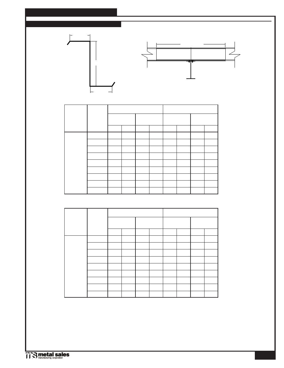
Load TaBLeS For STandard ZeeS
(Symmetrical Flanges Only)
3'-6" Lap
Flange
Web
Flange
Max Lap
26 86 142 110
180 168
Span in
Feet
Section
Max Lap - 2 Spans
Z-
8" x 3
1
/
2
"
Stress
Controlling, plf
12 Ga
14 Ga
12 Ga
14 Ga
Defl. (L/180)
Controlling, plf
16 250
448 300
480
Max Lap - 3 Spans
Stress
Controlling, plf
Defl. (L/180)
Controlling, plf
12 Ga
14 Ga
12 Ga
14 Ga
18 194
337 240
380
20 154
260 193
300
22 124
210 158
250
24 102
170 130
212
25 94 155 120
194 190
28 74 120
93 152 90 135
30 63 102
81 130 73 110
28 80 142 102
180 162
Span in
Feet
Section
Max Lap - 2 Spans
Z-
9" x 3"
Stress
Controlling, plf
12 Ga
14 Ga
12 Ga
14 Ga
Defl. (L/180)
Controlling, plf
18 202
391 261
449
Max Lap - 3 Spans
Stress
Controlling, plf
Defl. (L/180)
Controlling, plf
12 Ga
14 Ga
12 Ga
14 Ga
20 163
305 209
363
22 133
245 171
299
24 111
201 142
250
25 102
183 130
230 229
26 94 167 119
212 203
30 69 122 88 154 131
32
60
105
77
133
72
108
Notes:
1. Tabulated values are allowable superimposed loads. Purlin and all other load weights have not been subtracted from them.
2. Allowable loads have been calculated in accordance with 1996 AISI Specifications.
3. Bearing must be checked using actual bearing length and loads.
4. Wind loads can be obtained by multiplying tabulated values by 1.33.
5. Tabulated values are valid only if the compression flange of the section is adequately supported laterally.