8 gearbox, 9 brake, Gearbox – Lenze 931W User Manual
Page 36: Brake, Software implementation and parameter setting
Software implementation and parameter setting
Service menu
Gearbox
5
36
HB 13.0001-EN 3.0
5.3.8
Gearbox
Direction reversal
By means of this item, a reversal of the direction of rotation caused by the gearbox can be
compensated or considered. If a linear axis is used, the orientation of the limit switches
does not change, the use of the ”Direction reversal” function may also depend on the
mounting direction of the motor.
Input/output
The input/output ratio refers to the speed and identifies the ratio of the gearbox. If input
< output, a high gear ratio is available, accordingly if input > output, this is referred to as
a reduction.
5.3.9
Brake
Selecting the brake
If a brake is available, the brake function can be controlled via the system electronics by
confirming the parameter ”Available”. The actual operation of the brake then is defined in
the ”Travel data sets” menu
_к~вЙ гЙем
3
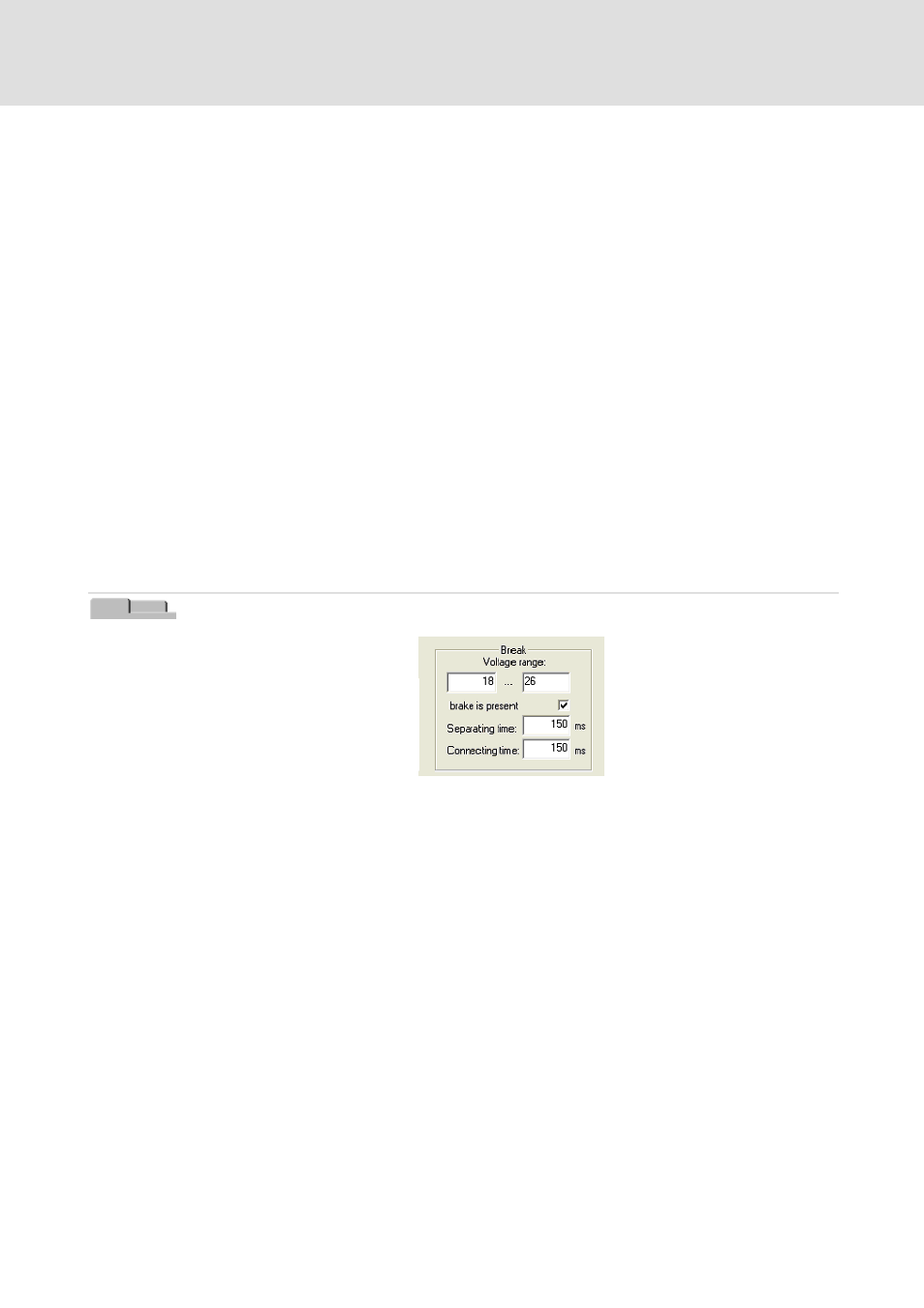
Voltage range
In the fields under ”Voltage range”, on the left the minimum brake voltage, and on the
right the maximum brake voltage can be entered. The minimum brake voltage can be set
between 18 and 22 V, and the maximum brake voltage can be set between 26 and 32 V.
Disengagement time
The disengagement time is the time unit which is used for opening the brake. At the
beginning of a travel data set, the motor and brake are immediately energised; the travel
program, however, only starts after the disengagement time has elapsed. This is intended
to prevent that the full motor torque unintentionally is positioned on the closed brake. A
minimum disengagement time of 150 ms is recommended. This time is
system-dependent.