Special handling of system variables, Function block library lenzeelectricalshaft.lib, Preface and general information – Lenze DDS Global Drive PLC Developer Studio User Manual
Page 9: 3 special handling of system variables
Function block library LenzeElectricalShaft.lib
Preface and general information
1−5
l
LenzeElectricalShaft.lib EN 1.2
1.2.1.2
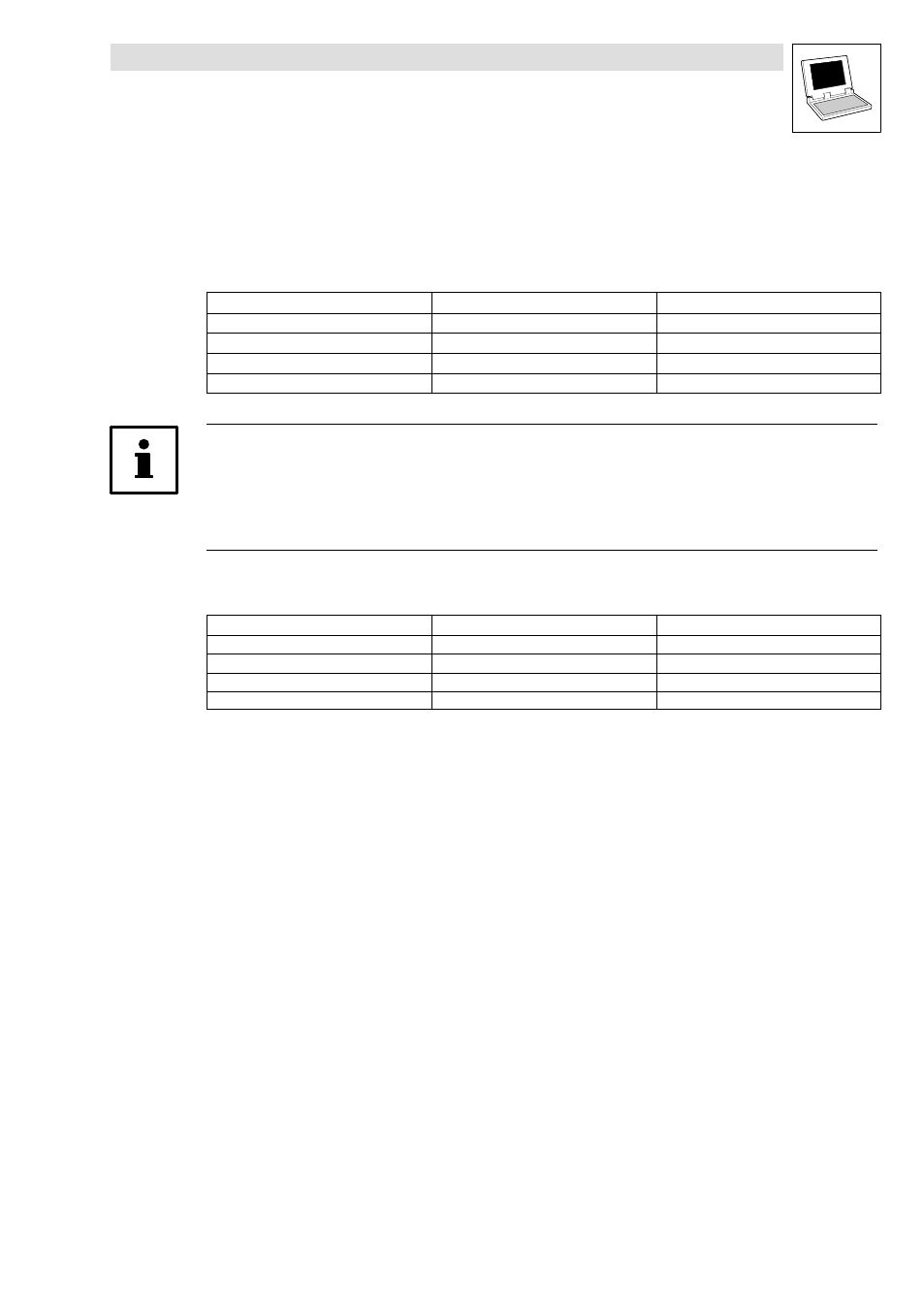
Designation of the signal type in the variable name
The inputs and outputs of the Lenze function blocks each have a specific signal type assigned. These
may be: digital, analog, position, or speed signals.
For this reason, each variable name has an ending attached that provides information on the type of
signal.
Signal type
Ending
Previous designation
analog
_a (analog)
H
digital
_b (binary)
G
Phase−angle difference or speed
_v (velocity)
F
Phase−angle or position
_p (position)
E
Tip!
Normalizing to signal type phase−angle difference/speed: 16384 (INT)
¢ 15000 rpm
Normalizing to signal type analog: 16384
¢ 100 % ¢ value under [C0011] = n
max
Normalizing to signal type angle or position: 65536
¢ 1 motor revolution
Examples:
Variable name
Signal type
Type of variable
nIn_a
Analog input value
Integer
dnPhiSet_p
Phase signals
Double integer
bLoad_b
Binary value (TRUE/FALSE)
Bool
nDigitalFrequencyIn_v
Speed input value
Integer
1.2.1.3
Special handling of system variables
System variables require special handling, since the system functions are only available for the user
as I/O connections in the control configuration.
In order to be able to access a system variable quickly during programming, the variable name must
include a label for the system function.
For this reason, the name of the corresponding system block is placed before the name of the
variable.
Examples:
AIN1_nIn_a
CAN1_bCtrlTripSet_b
DIGIN_bIn3_b