1 motor plug connection assignment, 2 power connections, Feedback system – Lenze MDxMA-MHxMA-MFxMA-MDERA-MHERA Three-phase AC motors User Manual
Page 37: Plug connectors, Electrical installation
Electrical installation
Plug connectors
Motor plug connection assignment
l
37
BA 33.0005−EN 2.0
6.4.1
Motor plug connection assignment
)
Note!
When making your selection, the motor data and permissible currents of the
cables according to the system cable system manual must be observed.
6.4.2
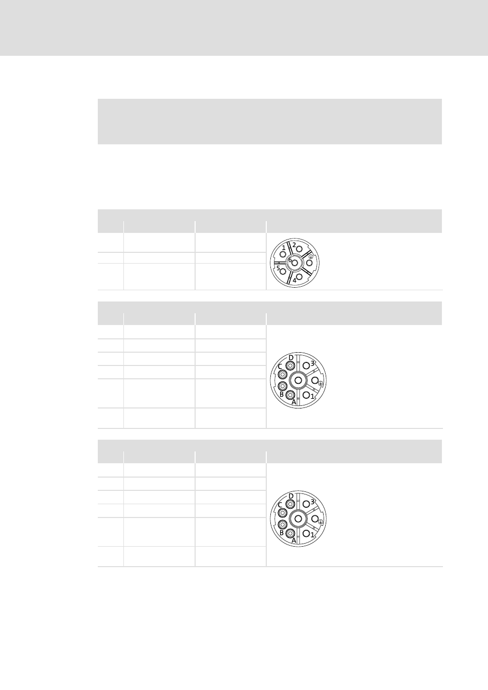
Power connections
Power / brake / thermal sensor
ICN, 6−pole and 8−pole
6−pole (external view of poles)
Pin
Standard description
Meaning
M23
1
2
BD1 / BA1
BD2 / BA2
Brake + /
~
Brake − /
~
MT−Steckverbinder−001.iso/dms
+
PE
PE conductor
4
5
6
U
V
W
Power phase U
Power phase V
Power phase W
8−pole (external view of poles)
Pin
Standard description
Name
M23
1
U
Power phase U
MT−Steckverbinder−001.iso/dms
+
PE
PE conductor
3
W
Power phase W
4
V
Power phase V
A
B
TB1 / TP1 / R1
TB2 / TP2 / R2
Thermal sensor TCO /
PTC / + KTY
TCO / PTC / − KTY
C
D
BD1 / BA1
BD2 / BA2
Brake + /
~
Brake − /
~
8−pole (external view of poles) / connection variant ICN 8B
Pin
Standard description
Name
M23
1
U
Power phase U
MT−Steckverbinder−001.iso/dms
+
PE
PE conductor
3
W
Power phase W
4
V
Power phase V
A
B
TB1 / TP1 / R1
TB2 / TP2 / R2
Thermal sensor TCO /
PTC / + KTY
TCO / PTC / − KTY
C
D
BD1 / BA 1
BD2 / BA2
Rectifier: Switching
contact
Connection variant ICN 8B − switching contact of the rectifier for DC switching. Rectifier
supply via motor terminal board. Only possible during mains operation!