2 brake connection, Electrical installation – Lenze MDxMA-MHxMA-MFxMA-MDERA-MHERA Three-phase AC motors User Manual
Page 35
Electrical installation
Wiring according to EMC
Brake connection
l
35
BA 33.0005−EN 2.0
Temperature monitoring
Terminal strip / terminal board
Meaning
Designation in accordance with EN 60034−8 Note
Thermal contact TCO
TB1
Max. 250 V~
Max. 1.6 A~
TB2
PTC thermistor
TP1
TP2
Thermal sensor +KTY R1
Observe polarity
Thermal sensor −KTY
R2
Terminal board or terminal possible for all thermal sensors
Blowers via blower terminal box / motor terminal box
External blower 3~
Terminal
board/terminal
Meaning
Note
U1
Connection to L1 − mains
Observe direction of rotation! In case of
incorrect rotation, interchange L1 − L2
V1
Connection to L2 − mains
W1
Connection to L3 − mains
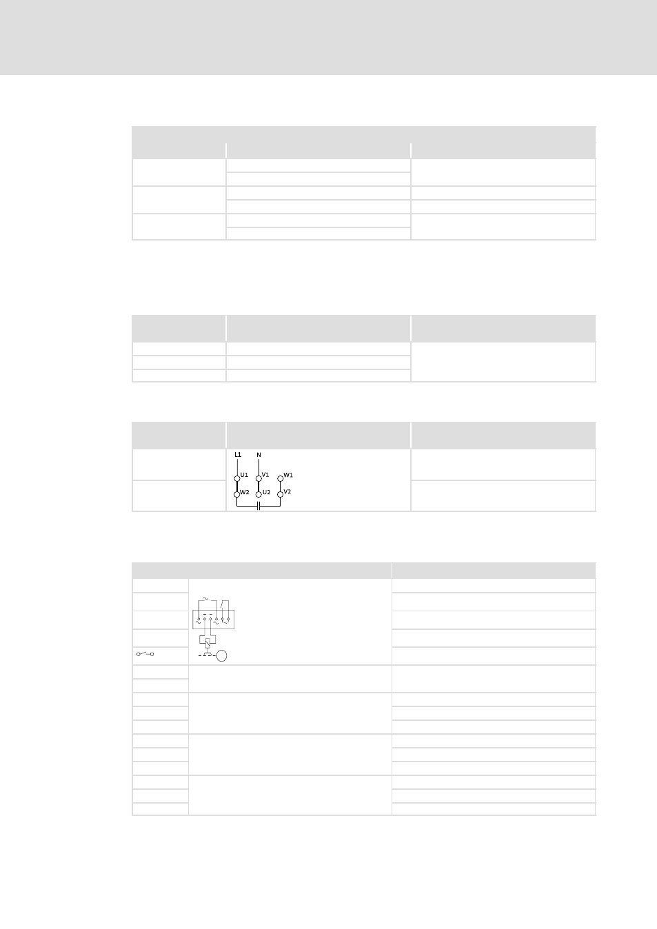
External blower 1~
Terminal board /
terminal
Meaning
Note
U1
Connection to L1− mains
V1 / U2
Connection to N − mains
6.3.2
Brake connection
Terminal
Meaning
Add−on
~
AC−excited brake (rectifier)
Connection to L1 − mains
~
M
3~
Connection to N − mains
+
Brake connection
−
Brake connection
Switching contact, DC switching
BD1
Brake, DC operated
DC connection
BD2
MS1
Brake microswitch, release control
Two−way switch (black)
MS2
NC contact (brown)
MS4
NO contact (blue)
MS1
Brake microswitch, wear control
Two−way switch (black)
MS2
NC contact (blue)
MS4
NO contact (brown)
MS1
Brake microswitch, manual release
Two−way switch (black)
MS2
NC contact (blue)
MS4
NO contact (grey)