Figure 3-25: angle adjustment plate installation – Landoll 2410 Weatherproofer I User Manual
Page 49
ASSEMBLY INSTRUCTIONS
3-31
Finishing Combo w/ Conditioner
Reel Installation (Option)
NOTES
Refer to Figure 3-19 for hydraulic diagram for the
2410-6-24 model.
Refer to Figure 3-20 for hydraulic diagram for the
2410-7-24 model.
Refer to Figure 3-21 for hydraulic diagram for the
2410-9-24 model.
See Figure 2-5 for finishing combo w/ conditioner reel
placement dimensions.
1.
Attach two combo attachment harrow arms to rear of
frame using 1-8 x 7-1/2 hex head cap screws and
hex lock nuts (See Figure 3-24.)
2.
Install the manifold to the manifold bracket on the
rear of frame using 1/2-13 x 3-1/2 hex head cap
screws and hex lock nuts.
3.
Install fittings into manifold according to Figures 3-19
thru 3-21.
4.
Install hoses per Figures 3-19 thru 3-21.
5.
Install steel plugs in any remaining open manifold or
valve ports.
6.
Pull out 1-8 x 7 hex head cap screw and attach
wrench combo plate to frame using the existing
hardware.
7.
Install wrench harrow adjustment plate to wrench
combo plate using quick hitch pin.
8.
Attach combo attachment harrow arms to 3 row coil
tine harrow assembly using spring clamp u-bolts,
harrow stiffener plates, and 5/8-11 flange head
serrated nuts.
9.
Attach combo attachment harrow arms to the
conditioner reel/gang bar assembly using gang bar
mount plate, 3/4-16 X 6 hex head cap screws and
double hex lock nuts.
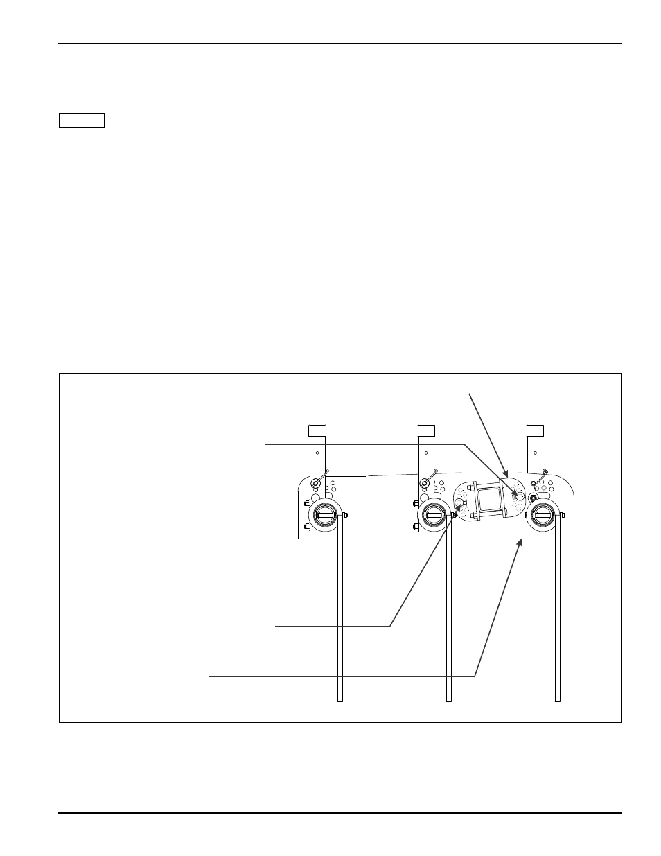
10. Install 1/2-13 x 1-1/4 round head square neck screws
through angle adjustment plate and gang bar plate
as shown in Figure 3-25.
Figure 3-25: Angle Adjustment Plate Installation
ANGLE ADJUSTMENT PLATE
1/2-13 X 1-1/4 RD HEAD SQ
NECK SCREW (PLACE IN
2ND INNER HOLE FROM TOP)
1/2-13 X 1-1/4 RD HEAD SQ
NECK SCREW (PLACE IN 2ND
INNER HOLE FROM BOTTOM)
GANG BAR PLATE
2410 combo angle adjustment plate