Kinze 3500 Lift and Rotate Planter Rev. 7/14 User Manual
Page 129
TM
Model 3500
M0240-01
6/11
6-33
Lubrication and Maintenance
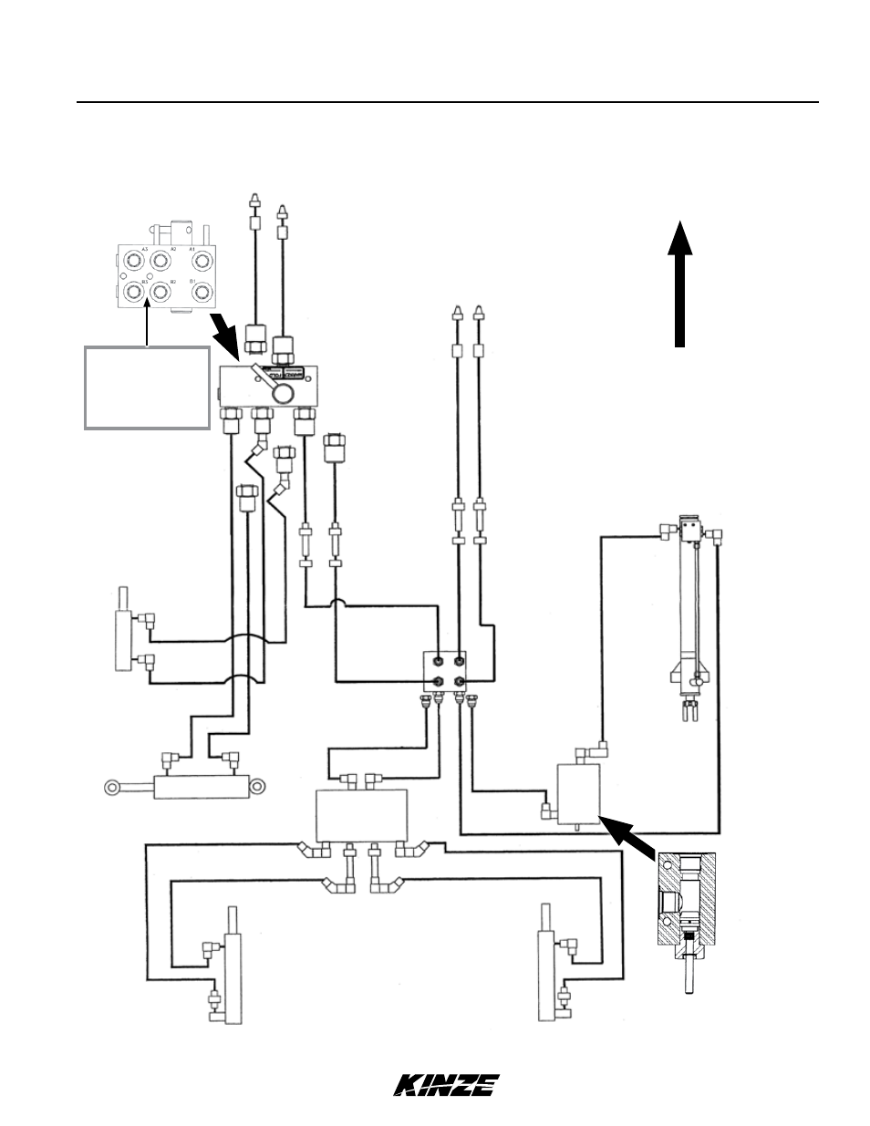
HYDRAULIC DIAGRAM - PLANTER
Transport
latch
cylinder
Lift
cylinder
Row marker
sequencing/
flow control
Rotation
cylinder
R.H.
marker
cylinder
L.H.
marker
cylinder
Selector
valve
Marker
Fold
A
B
A1
B1
A1
B1
A2
B2
A1
A1
A3
B3
C1
C1
D1
D1
D1
B1
C1
D1
C1
B1
.045" diameter
restrictor is located
between ports B3
and B2 to limit rotate
cylinder travel speed.
AA
AA
BB
Stroke
Limiter
Valve
Direction of tr
av
el
Blue I.D. sleeve
Red I.D. sleeve
Manifold block
R.H. side of
center post.
BB