JUMO 706030 LOGOPRINT 500 Printing Recorder Data Sheet User Manual
Page 3
2013-01-29/00355277
Data Sheet 706030
JUMO GmbH & Co. KG • 36035 Fulda, Germany
Page 3/12
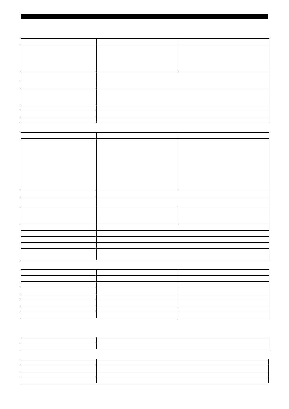
Resistance transmitter and potentiometer input
Input for DC voltage or DC current
Transducer short-circuit/break
Outputs
Printing system
Range
Accuracy
Measuring current
up to 200
up to 400
up to 800
up to 2000
up to 4000
±300m
±600m
±1
±2
±3
500
A
250
A
250
A
500
A
250
A
Connection type
resistance transmitter: 3-wire circuit
potentiometer: 2-, 3- or 4-wire circuit
Shortest span
6
Probe lead resistance
max. 30
per core in 4-wire circuit
max. 20
per core in 2-and 3-wire circuit
up to 200
range: max. 10 per core in 2-and 3-wire circuit
Resistance values
freely programmable within the limits in 0.1
steps
Measurement time
for 3 channels < 2sec; for 6 channels < 4sec
Input filter
2nd order digital filter; filter constant adjustable from 0 — 50.0sec
Basic range
Accuracy
Input resistance
-25 to
+75mV
0 — 100mV
-100 to +100mV
0 — 200mV
-500 to +500mV
0 —
1V
-1 to
+1V
-5 to
+5V
0 —
10V
-10 to
+10V
±100
V
±100
V
±150
V
±150
V
±1mV
±1mV
±2mV
±10mV
±10mV
±15mV
R
E
> 10 M
R
E
> 10 M
R
E
> 10 M
R
E
> 10 M
R
E
> 10 M
R
E
> 10 M
R
E
> 10 M
R
E
> 0.5 M
R
E
> 0.5 M
R
E
> 0.5 M
Shortest span
5mV
Range start/end
freely programmable within the limits
(up to 999mV in 0.01mV steps, from 1V in 1mV steps)
4 — 20mA
0 — 20mA
-20 to +20mA
±20
A
±20
A
±40
A
burden voltage
2.6V max.
burden voltage 2.6Vmax.
burden voltage 2.6Vmax.
Shortest span
0.5mA
Range start/end
freely programmable within the limits in 0.1mA steps
Measurement time
for 3 channels < 2sec; for 6 channels < 4sec
Input filter
2nd order digital filter; filter constant adjustable from 0 — 50.0sec
Features
adjustable linearizations for thermocouples and resistance thermometers
(for connection to transmitters without linearization)
Short-circuit
1
Break
1
Thermocouple
not recognized
recognized
Resistance thermometer
recognized
recognized
2
Resistance transmitter
recognized
recognized
Potentiometer
not recognized
recognized
2
Voltage up to ± 1V
not recognized
recognized
Voltage above ± 1V
not recognized
not recognized
Current
not recognized
not recognized
1
The print head is positioned to 0%, “>>>>>>” appears in the LED dot-matrix display.
2
In 4-wire circuit: only recognized at terminals 1 and 2.
Three open-collector outputs
to signal over/underlimit
One open-collector output
to signal faults (e. g. end of chart)
Drive
stepper motor
Sensitivity
0.2% or better referred to 100mm writing width
Reproducibility
0.25% or better referred to 100mm writing width
Display and recording accuracy
Class 0.5 referred to range limits and basic ranges