6 technical data (extract from data sheet) – JUMO 706585 LOGOSCREEN fd Recorder with stainless steel front Installation Instructions User Manual
Page 34
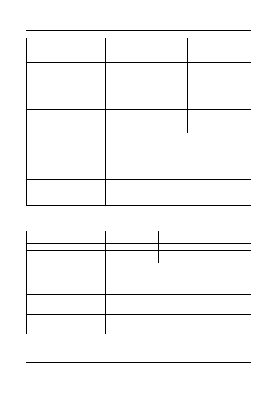
6 Technical data (extract from data sheet)
34
Resistance transmitter and potentiometer
Ni100 DIN 43760
(TC = 6.18*10
-3
1/°C)
2-/3-wire, 4-wire -60 to +180 °C
±0.4 °C
250 µA
Pt50 ST RGW 1057 1985
(TC = 3.91*10
-3
1/°C)
2-/3-wire
2-/3-wire
4-wire
4-wire
-200 to +100 °C
-200 to +1100 °C
-200 to +100 °C
-200 to +1100 °C
±0.5 °C
±0.9 °C
±0.5 °C
±0.6 °C
250 µA
250 µA
250 µA
250 µA
Cu50
(TC = 4.26*10
-3
1/°C)
2-/3-wire
2-/3-wire
4-wire
4-wire
-50 to +100 °C
-50 to +200 °C
-50 to +100 °C
-50 to +200 °C
±0.5 °C
±0.9 °C
±0.5 °C
±0.7 °C
250 µA
250 µA
250 µA
250µA
Cu100 GOST 6651-94 A.4
(TC = 4.26*10
-3
1/°C)
2-/3-wire
2-/3-wire
4-wire
4-wire
-50 to +100 °C
-50 to +200 °C
-50 to +100 °C
-50 to +200 °C
±0.5 °C
±0.9 °C
±0.5 °C
±0.6 °C
250 µA
250 µA
250 µA
250 µA
Connection circuit
2-, 3-, or 4-wire circuit
Shortest span
15 °C
Sensor lead resistance
max. 30 per conductor for 3-wire/4-wire circuit
max. 10 per conductor for 2-wire circuit
Range start/end
freely programmable within the limits, in 0.1 °C steps
Sampling cycle
Channel 1 to 18: 125 ms in total
Input filter
2nd order digital filter; filter constant adjustable from 0 to 10 sec
Electrical isolation
see “Electrical data” on page 37 and
“Overview of the electrical isolation” on page 20
Resolution
> 14 bit
Features
also programmable in °F
a
The linearization accuracy refers to the maximum measuring range. The linearization accuracy is reduced
with short spans.
Designation
Measuring range
Accuracy
a
a
The linearization accuracy refers to the maximum measuring range. The linearization accuracy is reduced
with short spans.
Measurement
current
Resistance transmitter
up to 4000
±4
100 µA
Potentiometer
to 4000
±400 m
±4
250 µA
100 µA
Connection circuit
resistance transmitter: 3-wire circuit
potentiometer: 2-/3-/4-wire circuit
Shortest span
60
Sensor lead resistance
max. 30 per conductor for 4-wire circuit
max. 10 per conductor for 2-/3-wire circuit
Resistance values
freely programmable within the limits, in 0.1 steps
Sampling cycle
Channel 1 to 18: 125 ms in total
Input filter
2nd order digital filter; filter constant adjustable from 0 to 10.0 sec
Electrical isolation
see “Electrical data” on page 37 and
“Overview of the electrical isolation” on page 20
Resolution
> 14 bit
Designation
Connection
circuit
Measuring range
Accuracy
a
Measurement
current