Instrument description – JUMO 706585 LOGOSCREEN fd Data Sheet User Manual
Page 7
2012-07-31/00586136
Data Sheet 706585
Page 7/21
JUMO GmbH & Co. KG
Delivery address: Mackenrodtstraße 14
36039 Fulda, Germany
Postal address:
36035 Fulda, Germany
Phone:
+49 661 6003-0
Fax:
+49 661 6003-607
E-mail:
Internet:
www.jumo.net
JUMO Instrument Co. Ltd.
JUMO House
Temple Bank, Riverway
Harlow, Essex CM20 2DY, UK
Phone: +44 1279 635533
Fax:
+44 1279 635262
E-mail:
Internet: www.jumo.co.uk
JUMO Process Control, Inc.
8 Technology Boulevard
Canastota, NY 13032, USA
Phone: 315-697-5866
1-800-554-JUMO
Fax:
315-697-5867
E-mail:
Internet: www.jumousa.com
Instrument description
Hardware
The paperless recorder is built to a modular
design. The basic type consists of a PSU
board (incl. relays) and a CPU board (incl.
Ethernet and RS232/RS485 interfaces and an
RS232 interface for barcode reader and USB
interface connection).
Module slots 1, 2 and 3 can be fitted with
input modules, each with 6 analog inputs or 3
analog inputs and 8 binary inputs/outputs.
Alternatively, module slot 3 can be fitted with
a relay module that has 6 relays.
Optionally, the PSU board can be equipped
with a PROFIBUS-DP interface.
Data recording
Measurements are acquired continuously in a
125msec sampling cycle. Based on these
measurements, reports are compiled and
limits checked.
The measurements are transferred to the
main memory of the instrument, according to
the programmable storage cycle and stored
value (maximum, minimum, average,
min&max, instantaneous value or economy
mode).
The paperless recorder saves the data in
groups, and an input can be assigned to
several groups (maximum 9).
Main memory (SRAM)
The data stored in the SRAM are regularly
copied to the internal memory in 20 kbyte
blocks.
Internal memory
When a block in the main memory has been
filled, it is copied to the internal memory. The
internal memory has a capacity of max.
256 Mbytes.
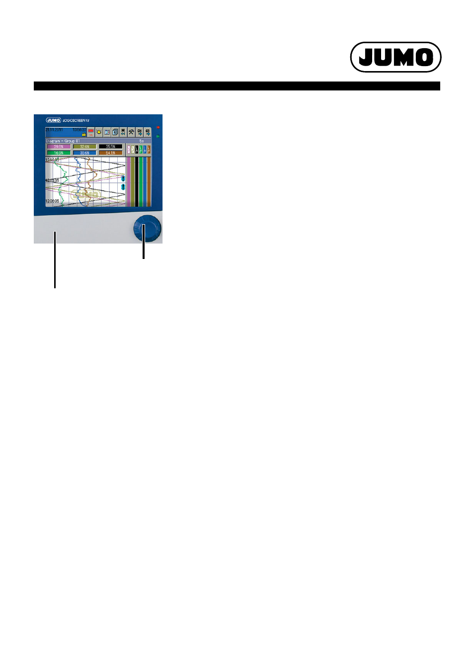
CompactFlash memory card
and USB interfaces behind
housing door.
Control knob, to rotate
and press.
Every write action is monitored, so that any
errors in saving the data can be immediately
identified.
The instrument monitors the capacity of the
internal memory and activates one of the
"memory alarm" signals when the capacity
falls below the configurable residual capacity
level. These signals can be used, for instance,
to operate the alarm relay.
The memory is written as a ring memory, i. e.
when the memory is full, the oldest data are
automatically overwritten by the new data.
Data from the internal memory can be shown
as a history presentation on the recorder. The
size of the history memory can be configured.
Data transfer to the PC
Data transfer from the paperless recorder to a
PC is made by means of the external
CompactFlash memory card (not available
with stainless steel front), the USB memory
stick or via one of the interfaces (USB device,
RS232, RS485, Ethernet).
Data security
The data are stored in coded form in a
proprietary format. This ensures a high level of
data security.
If the paperless recorder is disconnected from
the supply, then:
•
RAM and clock time are buffered by a
lithium battery (ex-factory)
10 years or
with a storage capacitor
2 days
(ambient temperature -40 to +45 °C),
•
measurement and configuration data in
the internal memory will not be lost.
Recording duration
Depending on the configuration of the
instrument, the duration of the recording can
vary over a considerable range (from a few
days up to several months).
Report
For each channel of a group, a report
(maximum/minimum/average or integrator)
can be run over defined periods.
Batch reports
Up to three batch reports can be created
simultaneously in the recorder. The
measurement data, start, end and duration of
each batch can be displayed together with a
batch counter and freely definable texts, both
on the recorder and within the PC Evaluation
Software PCA3000.
On request, a barcode reader can be used to
start batches and read in batch texts.
Limit checkline
changeover of operating mode
Over/underlimit conditions trigger alarms. An
alarm can be used, for instance, as a control
signal for changing over the operating mode.
The storage cycle and stored value can be
configured separately for all three operating
modes.
With the help of the alarm delay function, brief
occurrences or over/underlimit conditions
can be filtered out, with the result that no
alarm is generated.
Normal operation
If the instrument is not in timed or event
operation, normal operation is active.
Event operation
Event operation is activated/deactivated by a
control signal (binary input, group/
combination alarm, ...). As long as the control
signal is active, the instrument is in event
operation.
Timed operation
Timed operation is active on a daily basis
within a programmable time period. The
operating modes have different priorities.
Counters/integrators
27 additional internal channels are available
for use as counters, integrators, operating
time counters or for flow measurements.
These counters are controlled through the
binary inputs, the alarms, or via the logic
channels. The analog channels can be used
for the integrators.
The numerical indication is shown in a
separate window, with a maximum of 9 digits.
The acquisition period can be selected as:
periodic, daily, weekly, monthly, yearly as well
as external, total (overall count) or daily from
... to.
A maximum of 6 binary inputs are available as
high-speed counters with a 10 kHz sampling
cycle rate.
Math/logic module
(extra code)
The module for math and logic (18 channels
each) enables, for instance, the combination
of analog channels with one another, and also
the combination of analog channels with
counters and binary inputs. The operators
available for formulae are: +, -, *, /, SQRT(),
MIN(), MAX(), SIN(), COS(), TAN(), **, EXP(),
ABS(), INT(), FRC(), LOG(), LN(), humidity,
moving average or !, &, |, ^, as well as ( and ).
The math and logic module can only be
configured through the setup program.