2 electrical isolation, 3 connection diagram, Electrical isolation – JUMO 705030 mTRON T - Digital Input/Output Module Operating Manual User Manual
Page 24: Connection diagram, 4 electrical connection, 2 electrical isolation 4.3 connection diagram
4 Electrical connection
24
References to other information
•
The electromagnetic compatibility meets the standards and regulations cited in the techni-
cal data.
•
The USB device interface and voltage supply in the central processing unit 705001 are not
electrically isolated. In general, please observe the specifications regarding electrical isola-
tion.
4.2
Electrical isolation
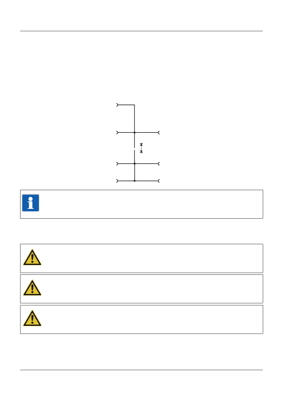
4.3
Connection diagram
AC 30 V
DC 50 V
»
External voltage supply DC 24 V
via terminal at the front
Voltage supply Out
Side
system bus In
Side system bus Out
Voltage
supply In
Digital inputs
Digital outputs
or
12
1
.
.
.
NOTE!
The external voltage supply for the digital input/output module 12-channel and the voltage sup-
ply for controlling the digital inputs of this module must be switched on/off with a common dis-
connecting device (common electrical circuit).
CAUTION!
At maximum load, the temperature may exceed 60 °C at the terminals.
As a result the insulation of the cable may be damaged.
The cable must be heat resistant up to at least 80 °C.
CAUTION!
Connecting the external voltage supply DC 24 V via the terminals at the front
(terminals “GND“ and “+24V“):
Ensure that the polarity is correct!
CAUTION!
The voltage of the digital outputs depends on the external voltage supply.
In case of undervoltage, no voltage is provided at the digital outputs.
Observe the technical data for the external voltage supply!