1 setting the switching functions – INFICON HPG400 ATM to High-Vacuum Gauge User Manual
Page 34
34
tina31e1 (2004-05) HPG400 v1.om
The gauges HPG400-SD and HPG400-SP have two independent, manually adjust-
able switching functions. Each switching function has a floating normally open relay
contact. The relay contacts are accessible at the sensor cable connector (
→ 18).
The threshold values of switching functions A and B can be set within the pressure
range 1×10
-9
mbar … 100 mbar via potentiometers "SETPOINT A" and
"SETPOINT B" (voltage settings representing pressures >100 mbar can be set, but
the relay trigger point will remain at 100 mbar).
U
Thresholdt
= 10 / 9 × (log p
Setpoint
– c) + 6
Where
U
p
c
[V]
[mbar]
0
[V]
[Pa]
2
[V]
[Torr]
-0.125
(
→ Appendix A).
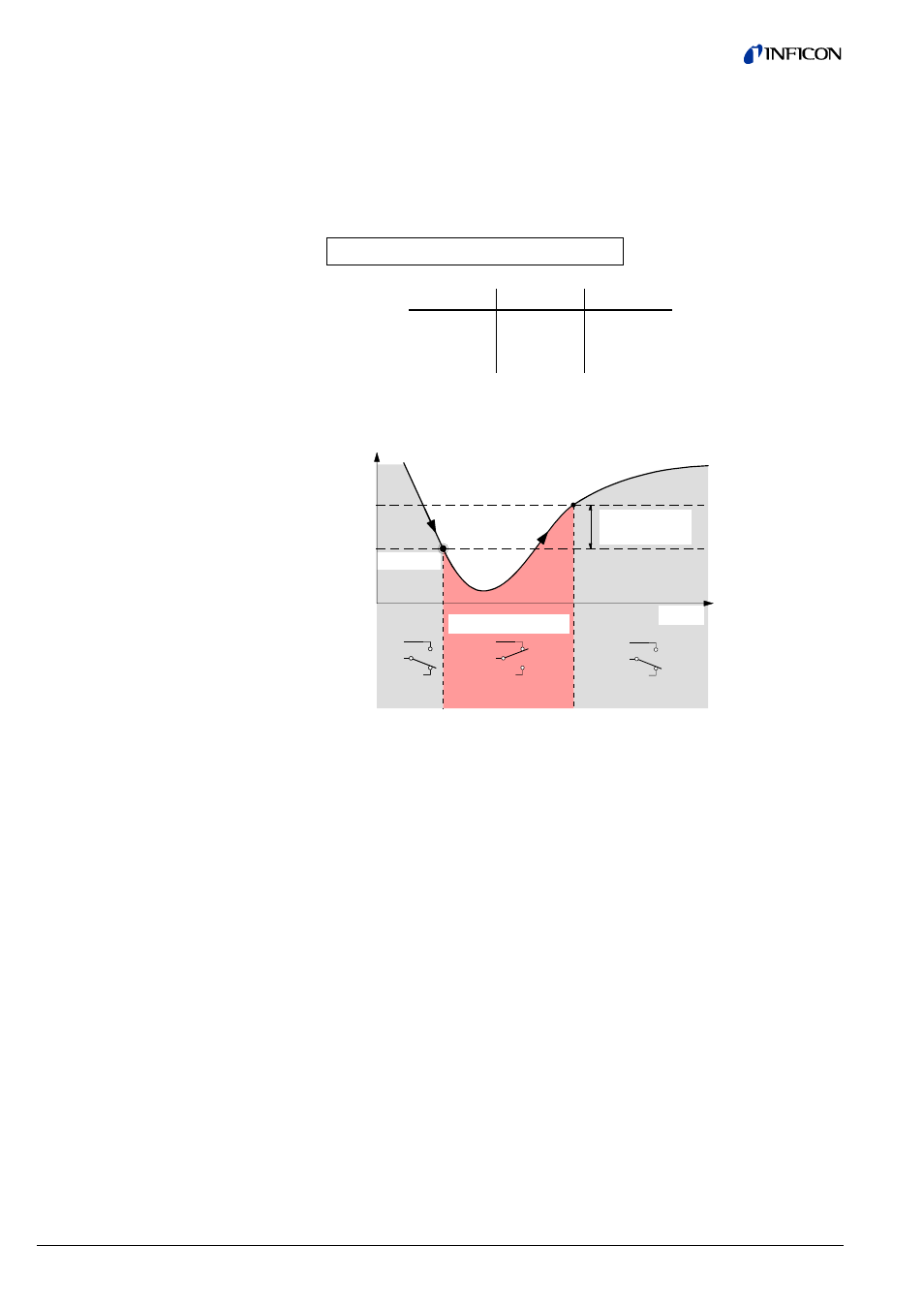
Time t
Off
Off
On
Hysteresis
10% U
Threshold
Switching function
Threshold
U
Measuring signal
(Pressure p)
(Setpoint A, B)
Me
asu
red va
lue
The hysteresis of the switching functions is 10% of the threshold setting.
The threshold values of the two switching functions "SETPOINT A" and
"SETPOINT B" are set locally on the potentiometers of the gauge that are acces-
sible via the openings on one side of the gauge housing.
• Voltmeter
• Ohmmeter or continuity checker
• Screwdriver, max. ø2.5 mm
4.8 Switching Functions
(HPG400-SD,
HPG400-SP)
4.8.1 Setting the Switching
Functions
Required tools