2 use with other controllers – INFICON HPG400 ATM to High-Vacuum Gauge User Manual
Page 17
tina31e1 (2004-05) HPG400 v1.om
17
The gauge can also be operated with other controllers.
Especially the fieldbus versions HPG400-SD (DeviceNet) and HPG400-SP
(Profibus) are usually operated as part of a network, controlled by a master or bus
controller. In such cases, the control system has to be operated with the appropri-
ate software and communication protocol (
→ [1] and [2]).
For reasons of compatibility, the expression "sensor cable" is used for all
HPG400 versions in this document, although the pressure reading of the
gauges with fieldbus interface (HPG400-SD or HPG400-SP) is normally
transmitted via DeviceNet or Profibus.
The sensor cable is required for supplying all HPG400 types with power.
In connection with the gauges with fieldbus interface (HPG400-SD and
HPG400-SP), it also permits access to the relay contacts of the switch-
ing functions (
→ 18, 34).
The application and length of the sensor cable have to be considered when deter-
mining the number and cross sections of the conductors (
→ 10).
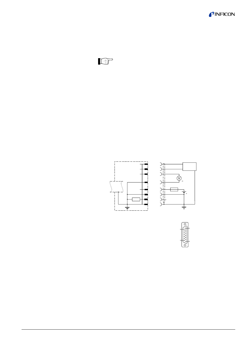
Open the cable connector (D-Sub, 15 pins, female).
Prepare the cable and solder/crimp it to the connector as indicated in the
diagram of the gauge used:
Electrical connection
Pin 2 Signal output (measuring signal) 0 … +10 V
Pin 5 Supply voltage common, GND
Pin 8 Supply voltage +24 VDC
Pin 10 Gauge identifcation
Pin 12 Signal common, GND
Pin 13 RS232C, TxD
Pin 14 RS232C, RxD
Pin 15 Shielding, housing, GND
Pins 1, 3, 4, 6, 7, 9 and 11
are not connected internally.
8
9
1
15
TxD
HPG400
56k
Ω
RxD
Measuring signal
+Ub
13
14
2
12
8
5
15
+
1.25AT
Identification
10
RS232C
+
24 V
D-Sub, 15 pins
female
soldering side
3.2.2 Use With Other
Controllers
3.2.2.1 Making a Sensor Cable
Cable type
Procedure
Sensor cable connection
HPG400