Chapter 2 installation, 1 introduction, 2 mounting the controller – INFICON CI-100 Crucible Indexer User Manual
Page 17: 1 full rack extender, Chapter 2, Chapter 2, installation
2 - 1
IP
N 07
4-
54
4-
P1
B
CI-100 Crucible Indexer Operating Manual
Chapter 2
Installation
2.1 Introduction
The CI-100 controller requires AC mains power, and should be located within 10 ft.
of the Motor drive unit. The Motor drive typically can be mounted to the E-Beam
indexer feedthrough shaft using the mounting bracket and flexible coupling
supplied.
NOTE: The CI-100 uses a four rotation full cycle. This means that after four full
turns of the motor, it is considered to be back at the home position. Crucible
gearing can be adjusted to match this requirement. For example, if you
have a four discrete pocket crucible, the gearing should be designed so
that one full turn of the CI-100 motor moves one pocket position. For eight
pockets, a half turn should move one pocket position.
2.2 Mounting the Controller
The CI-100 Controller is a 2U (3.5 in. high) half-rack wide instrument. It can be
mounted with a blank space on either side, using the optional Full Rack Extender.
Alternatively it can be mounted next to another 2U half-rack instrument, using the
optional Half Rack Adapter
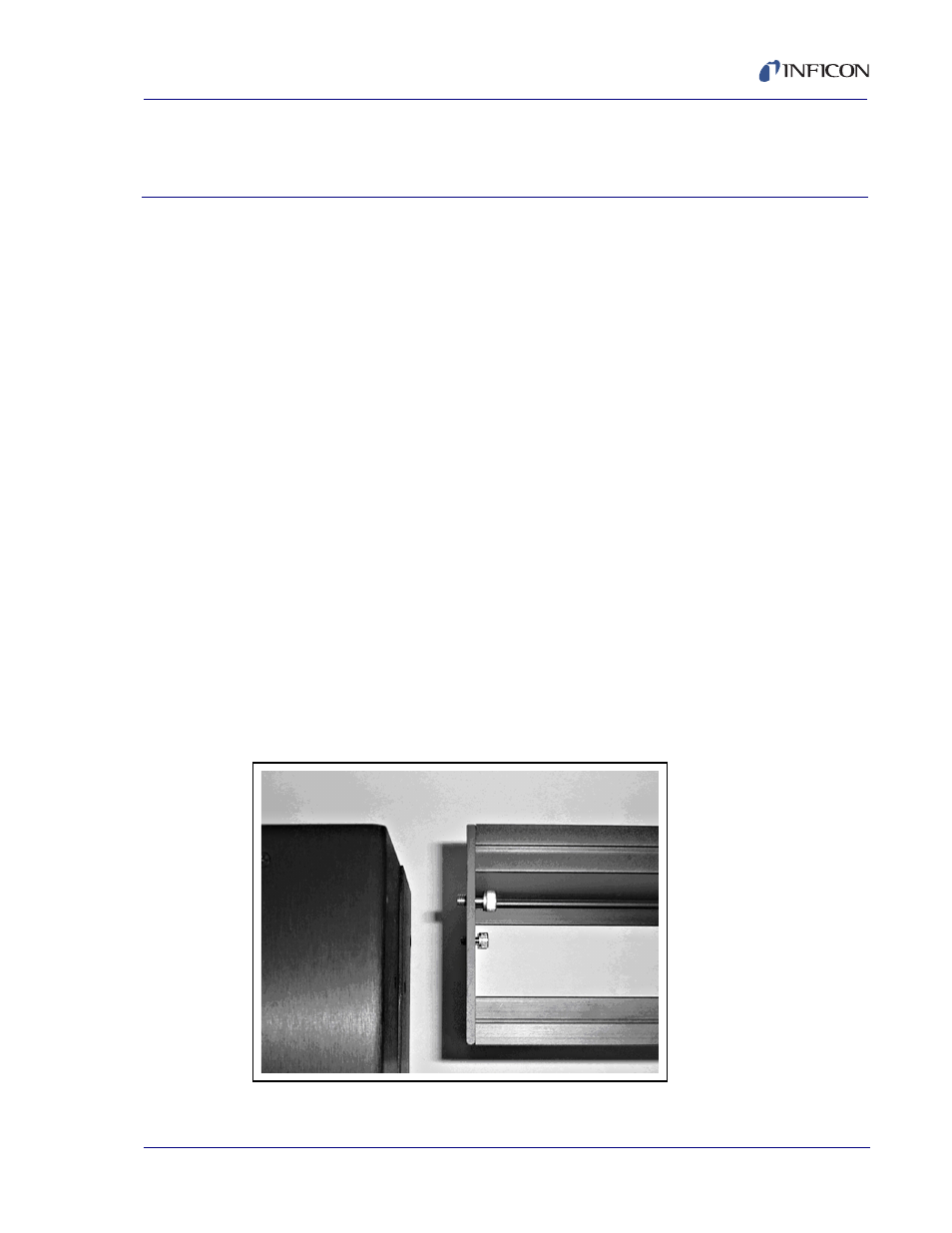
2.2.1 Full Rack Extender
Assemble the two extender side panels and the extender front and rear panels into
a box configuration using the eight 6-32 flat-head screws.
Figure 2-1 Full Rack Extender