Trouble shooting, Figure 5.1: signal flow diagram, Trouble shooting page 61 – INFICON SRT-422 Crucible Indexer User Manual
Page 63
Trouble Shooting
Page 61
0005
Section 5
Trouble Shooting
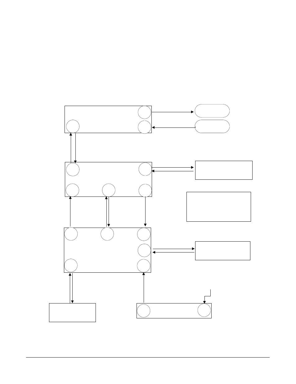
Section 5.1: SECTION OVERVIEW
The STC-422 should prove to be an extremely reliable and trouble free unit. However, the
troubleshooting checklist provided would help in resolving any problems that do occur. In
addition, the signal-flow diagram provided will make it possible to trace signals between
indexer components when problems must be tracked to their sources.
SRT-422 Interface PC Board
Index Drive Unit
P1
J1
J2
Motor
Encoder
SRT-422 Optoisolator
Interface PC Board
P1
P2
J2
J1
P3
Motor-Drive
Output Pulses
Position
Feedback
from Encoder
Position
Feedback
Motor-Drive and
Phase Control Output
SRT-422 Controller PC Board
J2
J3
J5
J1
J4
J6
Host Computer,
Deposition Controller, or other
external control device.
NOTE:
P2 on SRT-422 Optoisolator
Interface PC Board is rear-panel I/O
(ISOLATED) connector.
J6 on SRT Controller PC Board
is rear panel RS-232 connector
Pocket-Select and
System Interlock Inputs
Pocket-Position and
POCKET GOOD Outputs
Pocket Select and
System Interlock
inputs
Pocket-Position and
POCKET GOOD
Signals
Motor-Drive
Output Pulses
Position Feedback
from Encoder
Data In
Data Out
Host Computer,
Deposition Controller, or other
external control device.
Power Supply PC Board
J2
J1
Front Panel Controls and
LED Display
Power In
Pocket Position
Outputs to LED
Display
Inputs from Front
Panel Controls
120 or 240
VAC Power
Figure 5.1: Signal Flow Diagram