Page 42 installation – INFICON SRT-422 Crucible Indexer User Manual
Page 44
Page 42
Installation
2
Put the half-with control unit in place a 5-1/4-in-high space in the electronics rack.
3
Secure the front panel to the rack with the four screws and cup washers provided.
4
Connect the input power cable to the plug on the control unit’s rear panel.
5
Plug the other end of the power cable into a wall socket.
6
Make sure that the line voltage selection switch is set correctly (see Fig. 2-2)..
WARNING
Operating the SRT-422 with incorrect line voltage selected will
damage the unit.
7
Connect the male ‘D’ connector on one end of the motor cable to the MOTOR
connector on the control unit’s rear panel. Use the screws provided on the ‘D’
connector to secure it to the MOTOR connector.
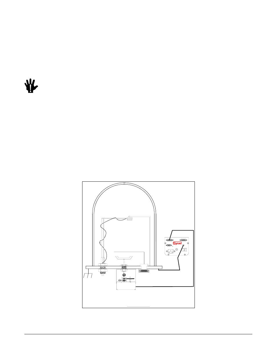
Section 3.11: Indexer and System Grounding
A grounding stud is provided on the control unit’s rear panel. Use a 16-gauge or larger wire
to ground this stud to the electronics rack. Because the rack as a whole is likely to be subject
to RF interference, it is strongly recommended that a low-impedance ground be provided for
the system. The figure below shows a method of setting up such a ground.
CHAMBER
Crystal Sensor
SHUTTER
Indexer
Chamber ground
To Control Unit
240VAC Fuse 1/8 AMP SB
120VAC Fuse 1/4 AMP SB
I/O (ISOLATED)
RS-232
MOTOR
Ready
SRT-422
instruments
Figure 3.9: SRT-422 Grounding