INFICON SRT-422 Crucible Indexer User Manual
Page 48
Page 46
Installation
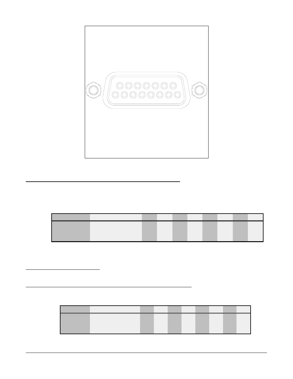
9 10 11 12 13 14 15
1 2 3 4 5 6 7 8
9 Pocket Position 0 output
10 +24 Vdc input
11 Not Used
12 Not Used
13 Not Used
14 Internal supply ground
15 External supply ground
1 Pocket Select 0 input
2 Pocket Select 1 input
3 System interlock input
4 Pocket Position 1 output
5 Pocket Good Output
6 External supply ground
7 Pocket Select 2 Input
8 Pocket Position 2 output
Figure 3.11: Pinout for the rear panel I/O (ISOLATED) connector
Pins 1, 2, and 7 (Pocket SELect Inputs 0,1, and 2 respectively)
When the front-panel MAN/AUTO switch is set to AUTO, these inputs control pocket selection
in multipocket modes and rotation speed in banana and continuous modes. Table 2-3 shows
the digital code required to select each pocket and correlates those codes to the pins 1 , 2, and
7.
1
2
3
4
5
6
7
8
LSB A Pin 1 (SEL 0)
0
1
0
1
0
1
0
1
B
Pin 2 (SEL 1)
0
0
1
1
0
0
1
1
MSB C Pin 7 (SEL 2)**
0
0
0
0
1
1
1
1
Table 3.5: Pocket-select codes input via pins 1, 2, and 7
**SEL2 not required for four pocket configurations
Pin 3 (System Interlock Input)
This is a user-defined interlock input. The drive motor cannot turn when this signal is true.
Pins 4, 8, and 9 (Pocket POSition Outputs 1, 2, and 0, respectively)
These outputs indicate the current pocket location. The Table below shows the digital code for
each pocket position and correlates those codes to pins 4, 8, and 9.
1
2
3
4
5
6
7
8
LSB
Pin 9 (POS0)
0
1
0
1
0
1
0
1
Pin 4 (POS1)
1
0
0
1
1
0
0
1
MSB
Pin 8 (POS2)
1
1
1
0
0
0
0
1
Table 3.6: Pocket-position codes output via pins 4, 8, and 9