INCRA Miter Express User Manual
Page 4
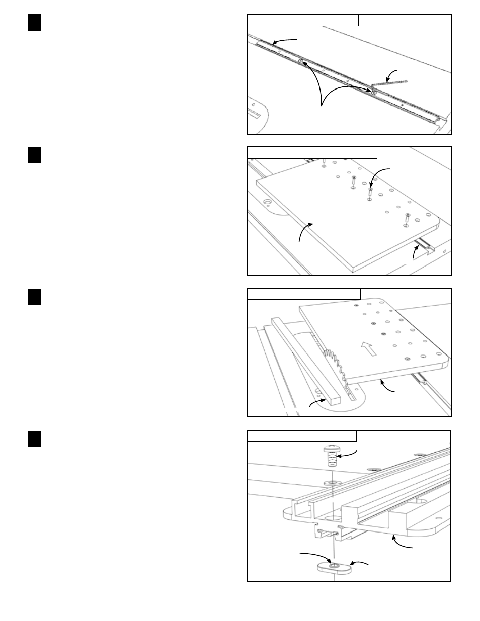
FIG. 10
Attach T‑slot retainers
FIG. 8
Attach drop panel to miter bar
FIG. 9
Cut off drop panel overhang
Attach Drop Panel to Aluminum Miter Bar
Using (4) #10-24 x ¾” Phillips flat head screws,
attach the drop panel to the aluminum miter bar. Use
the mounting holes that permit the least amount of panel
overhang beyond the line of cut, Fig. 8.
6
Cut Off Drop Panel Overhang
Raise the saw blade about ¾” and make a cut to
remove the portion of the drop panel that extends beyond
the line of cut, Fig. 9. Turn off the saw, lower the blade
and return the Utility Plate assembly to the table saw.
CAUTION: In use, only the Utility Plate assembly
slides to move your workpiece through a cut. The
drop panel will be positioned adjacent to the blade
and locked in place by tightening the (2) expansion
mechanisms to provide zero clearance and workpiece
cutoff support. (See Fig. 12)
7
Attach T-Slot Retainers
Note: Skip this step for non T-slot miter channels.
Open Hardware Pack C-14. Slide the Utility Plate panel
assembly to overhang the edge of your table saw and
attach the T-slot retainer using the #10-32 x
3
/
8
” Phillips
pan head screw as shown in Fig. 10.
The raised rim around the T-slot retainer’s threaded hole
should face upward. Repeat for the opposite end of the
Utility Plate.
8
4
FIG. 7
Adjust aluminum miter bar
Adjust Aluminum Miter Bar
Using the supplied
3
/
3 2
” hex key, adjust the aluminum
miter bar at each of the (2) expansion mechanism
locations for a good sliding fit in your table saw’s remaining
miter slot. Turning the screw clockwise expands the
mechanism. Expand a little at each of the locations until
the bar slides smoothly with no side play, Fig. 7.
5
Expansion
mechanisms
3
/
32
” Hex key
Aluminum miter bar
Drop panel
#10-24 x ¾”
Phillips flat head
screws
Miter bar
Drop panel overhang
Drop panel
#10-32 x ³/₈” Phillips pan head screw
Utility plate
T-Slot retainer
Raised rim face up