2 countertop cut-outs dimensions – Garland MO QU 28000 FL INDUCTION MODULE-LINE COOKTOPS DUAL/QUAD User Manual
Page 20
Installation
RTCSmp
Built-In
Module-Line Dual/Quad Cooktops
20
Part # 4532415 Rev 3 (8/19/14)
4.5
Coil Carrier Sheet, Ceran Glass and Mounting Frame
4.5.1
Location & Ventilation Requirements for Coil Carrier Sheet Installation
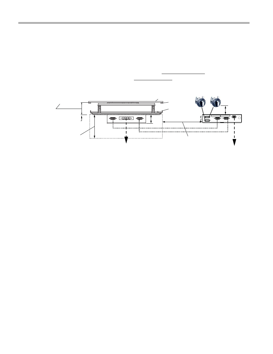
A Coil Carrier Sheet houses the induction coil and sensor assemblies, which are installed directly under
the glass-top.
Distance from the control unit to the coil carrier sheet: MAX. 31.50” / 800mm.
Clearance below the coil carrier sheet: MIN. 3.94” / 10 cm. This clearance must be maintained for
installation and service. Ensure this area can be easily accessible for maintenance and service.
MUST NOT install or store any metallic objects or components below the induction coils.
When placed in the vicinity of other coils, objects/components that are made of steel must be non-
magnetic.
Prevent moisture, hot ambient air or greasy fume being drawn into the installation compartment,
especially when the appliances are near a fryer or oven.
o
Maintain ambient temperature below 104
F (40C) for proper functioning of the unit.
o
Install extra fan in the compartment to remove any hot air away from the induction unit.
Keep all the combustible materials, vapors or liquids away from the coil carrier sheets.
4.5.2
Countertop Cut-outs Dimensions
NOTE: The cut-out dimensions are specified in the drawings of the mounting frames. These dimensions include
widths for silicone sealant, 4mm on each side.
A line of silicone sealant of 4mm wide must be applied around the glass perimeter to prevent any ingress of liquid
into the unit.
4.5.3
Correct Orientation – Coil Carrier, Glass and Frame
When designing a kitchen layout with quad models, ensure to orient the mounting frame correctly to allow for
ease of installation and service. See section 4.5.5 Installation Steps.
For any quad model with full coils, the orientation of the frame also needs to match the orientations of the glass
and the coil carrier sheets. Follow the chart below to ensure the correct placement is incorporated into the
kitchen design and installation.
49mm/
1.93”
Clearance Minimum
10 cm / 3.94”
Below Coil Carrier Sheet
Optimal contact pressure
of the coil carrier on
Ceran glass 5mm.
Ceran Glass
Silicone Gasket
Coil Carrier Sheet
To Induction
Generator
Distance Maximum
800 mm / 31.5”
Distance Maximum
800 mm / 31.5”
Coil Connection to
Generator
55 mm / 2.17” (without compression)
50 mm +/- 2mm (with correct compression
when installed)
- MO QU 24000 INDUCTION MODULE-LINE COOKTOPS DUAL/QUAD MO QU 21000 INDUCTION MODULE-LINE COOKTOPS DUAL/QUAD MO QU 20000 INDUCTION MODULE-LINE COOKTOPS DUAL/QUAD MO QU 14000 INDUCTION MODULE-LINE COOKTOPS DUAL/QUAD MO DU 14000 FL INDUCTION MODULE-LINE COOKTOPS DUAL/QUAD MO DU 10000 INDUCTION MODULE-LINE COOKTOPS DUAL/QUAD MO DU 7000 FL INDUCTION MODULE-LINE COOKTOPS DUAL/QUAD MO DU 7000 INDUCTION MODULE-LINE COOKTOPS DUAL/QUAD