Important, Clearance, Figure – Garland MO QU 28000 FL INDUCTION MODULE-LINE COOKTOPS DUAL/QUAD User Manual
Page 14
Installation
RTCSmp
Built-In
Module-Line Dual/Quad Cooktops
14
Part # 4532415 Rev 3 (8/19/14)
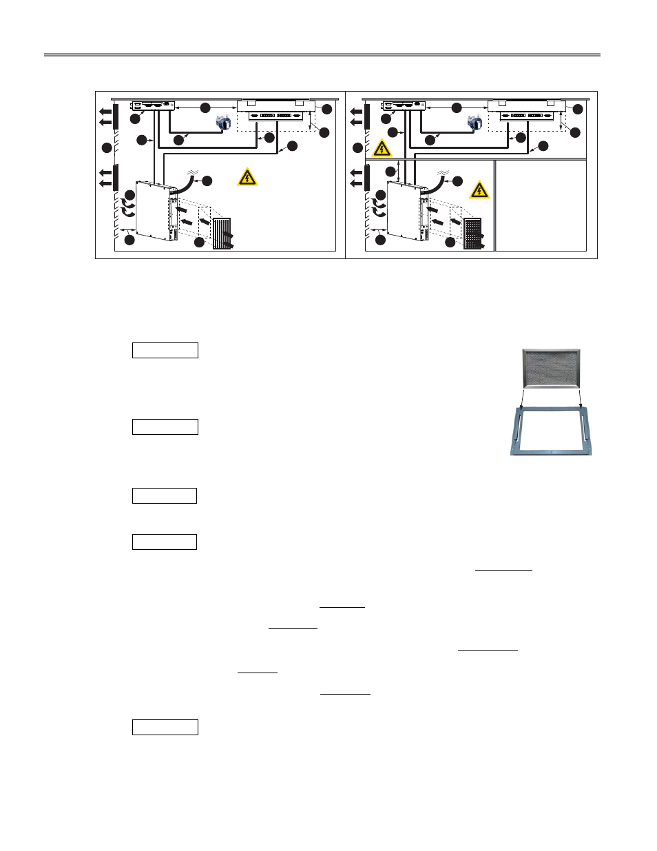
Figure (A) All components are installed inside one single compartment and the wires are exposed.
Figure (B) The interior space of the cabinet is divided. The coil carrier sheet, the control unit and their wiring
are protected inside the upper compartment; the generator and its wiring are protected inside
the lower compartment. Extra storage space can also be created.
(C)
IMPORTANT
Fresh air intake. It is recommended to isolate the fresh air intake
from the exhaust air via an air intake duct, an air outlet duct or both. Filter the
intake air with a removable air filter (right, an example).
(D) Hot air exhaust from the induction generator.
(E)
IMPORTANT
Air exhaust opening installed on the cabinet. It is highly
recommended to install a fan or fans on the cabinet to pull hot exhaust air away
from the electronic equipment. Buildup of hot exhaust air will cause the induction
unit to reduce power or to switch-off.
(F)
CLEARANCE
Minimum clearance, see section 4.2.2.
(G) A Coil Carrier Sheet and Mounting Frame.
(H)
CLEARANCE
Minimum clearance, see section 4.2.2.
(I)
Maximum distance between the control unit and the coil carrier sheet is 80 cm/31.5”. See (M).
(J) Control Unit.
(K) RJ45 CAN/BUS cable, standard length= 3m / 118” , to connect the control unit to the generator.
(L) Power switch cable, length= 0.9m / 36” , to connect the operation unit (power switch) to control unit.
Maximum distance between the control unit and the operation unit: 80 cm/31.5”.
(M) Sensor cable, length= 1m / 39” , to connect the sensors on the coil carrier sheet to the control unit.
(N) Induction coil cable, standard length= 2.5m / 98” , to connect the induction coils on the coil carrier
sheet to the generator.
IMPORTANT
Always route sensor and communication cables separately and away from the coil
cables.
(O) Main power cable connection. Power cable is not provided.
H
F
G
F
N
H
M
G
L
F
N
O
O
M
L
D
E
Figure
B
Figure
A
C
K
J
D
E
C
K
J
I
I
Air Intake Filter
Filter Holder
Filter Holder
- MO QU 24000 INDUCTION MODULE-LINE COOKTOPS DUAL/QUAD MO QU 21000 INDUCTION MODULE-LINE COOKTOPS DUAL/QUAD MO QU 20000 INDUCTION MODULE-LINE COOKTOPS DUAL/QUAD MO QU 14000 INDUCTION MODULE-LINE COOKTOPS DUAL/QUAD MO DU 14000 FL INDUCTION MODULE-LINE COOKTOPS DUAL/QUAD MO DU 10000 INDUCTION MODULE-LINE COOKTOPS DUAL/QUAD MO DU 7000 FL INDUCTION MODULE-LINE COOKTOPS DUAL/QUAD MO DU 7000 INDUCTION MODULE-LINE COOKTOPS DUAL/QUAD