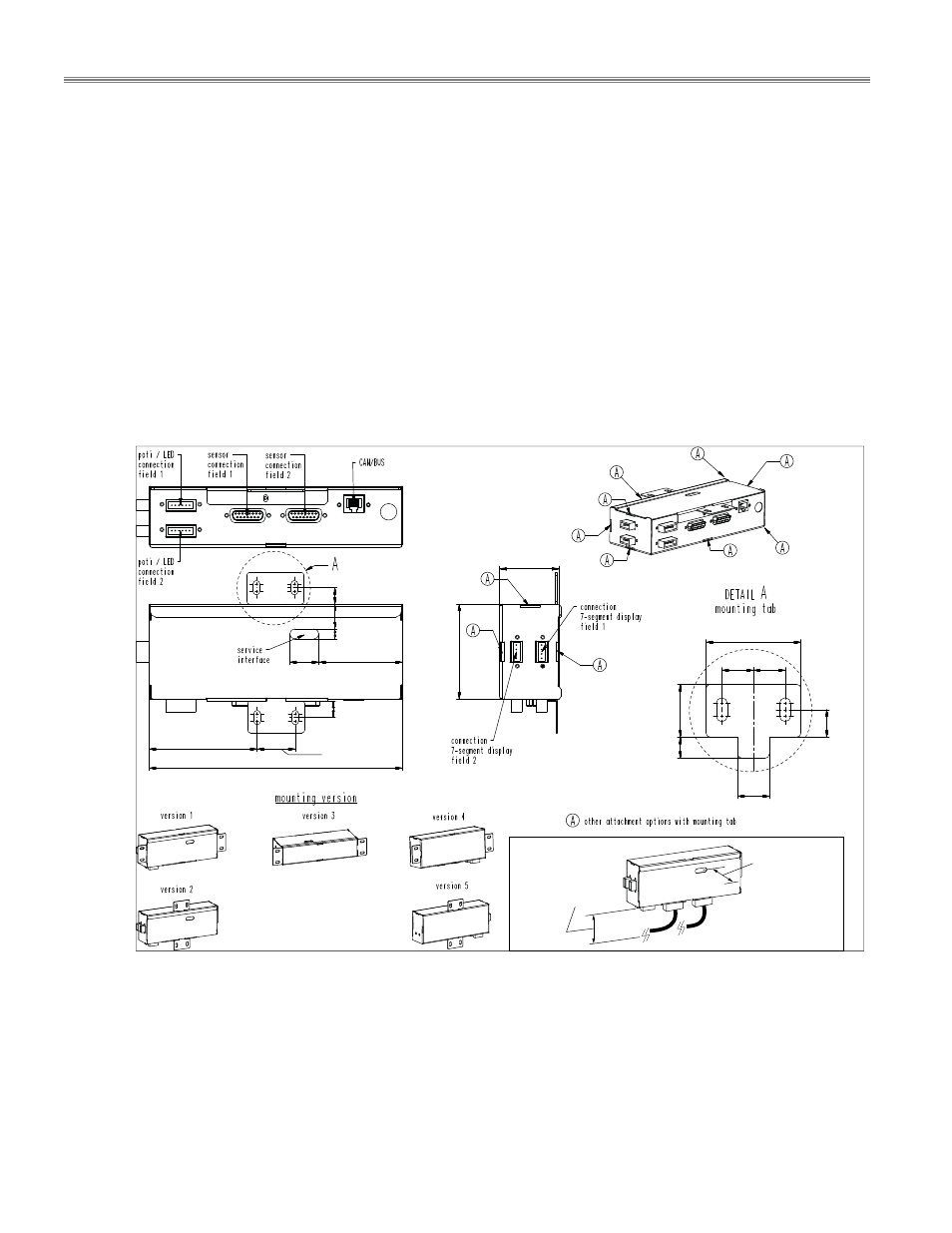
3 mounting methods, 4 dimensions – control unit – Garland MO QU 28000 FL INDUCTION MODULE-LINE COOKTOPS DUAL/QUAD User Manual
Page 18
Installation
RTCSmp
Built-In
Module-Line Dual/Quad Cooktops
18
Part # 4532415 Rev 3 (8/19/14)
4.4.3
Mounting Methods
Control Unit:
o
Installation brackets are provided to mount the control unit. See “Mounting Version” in section
4.4.4 Dimensions– Control Unit.
o
Mount the control unit directly onto the cabinet compartment wall/shelf, or
o
Stud-mount the control unit onto the back of the cabinet front panel. Use the dimensions
provided in section 4.4.5 Dimensions Guide as a template to install the control unit, the
operation units (power switches) and the LED Indicator lights.
o
Keep the Service Interface window on the control unit accessible for service.
IMPORTANT: To prevent the operation units (power switches) from rotating during operation,
secure these units onto the panel with two (2) M4 screws. See section 4.4.5 Dimensions Guide.
4.4.4
Dimensions – Control Unit
7.87” (200 mm)
3.35” (85 mm)
1.18” (30 mm)
0.51” (13 mm)
0.51” (13 mm)
2.60” (66 mm)
0.31” (8 mm)
0.79” (20 mm)
0.91”
(23 mm)
2.95”
(75 mm)
1.77” (45 mm)
0.59”
(15 mm)
0.39” (10 mm)
0.51”
(13 mm)
0.98” (25 mm)
0.59”
(15 mm)
0.59”
(15 mm)
1.85” (47 mm)
Cable Bend Radius/
Service Clearance
min 70mm / 2.75”
Service Interface
Clearance
min 38mm / 1.5”
- MO QU 24000 INDUCTION MODULE-LINE COOKTOPS DUAL/QUAD MO QU 21000 INDUCTION MODULE-LINE COOKTOPS DUAL/QUAD MO QU 20000 INDUCTION MODULE-LINE COOKTOPS DUAL/QUAD MO QU 14000 INDUCTION MODULE-LINE COOKTOPS DUAL/QUAD MO DU 14000 FL INDUCTION MODULE-LINE COOKTOPS DUAL/QUAD MO DU 10000 INDUCTION MODULE-LINE COOKTOPS DUAL/QUAD MO DU 7000 FL INDUCTION MODULE-LINE COOKTOPS DUAL/QUAD MO DU 7000 INDUCTION MODULE-LINE COOKTOPS DUAL/QUAD