Gamber-Johnson 7170-0164 User Manual
Page 3
3 of 4
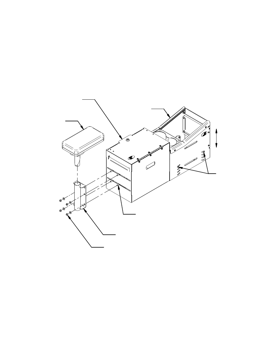
The Vertical Surface Mount is attached to the end of the File Box.
(4) .25-20 x .75 Carriage Bolts are inserted from the inside of the File Box and (4) Flat Washers
and (4) Nylok Nuts installed on the outside.
The Armrest or Armrest Printer is inserted and secured in position by tightening the 3/8 bolt.
See Fig 3
2.4"
Adjustment
Armrest or
Armrest Printer
Vertical Surface Mount
Insert (4) .25-20 x .75 Carriage Bolts
from inside of File Box
(4) .25 Flat Washers
(4) .25-20 Nylok Nuts
File Box
Console Box
.25-20 x .50
Button Head Screws
Install the control heads, accessories and blank panels into the console box.
Assemble faceplates to control heads as described in instruction sheet INST-3. (see page 4)
Electrically connect the equipment at this time, allowing extra wire length for servicing the
equipment.
Fig 3