Gamber-Johnson 7160-0425 User Manual
Installation instructions, Product revision form, Fig. 1
Product Mounting Disclaimer
Gamber-Johnson is not liable under any theory of contract or tort law for any loss, damage, personal injury, special, incidental or consequential damages for personal injury or other damage
of any nature arising directly or indirectly as a result of the improper installation or use of its products in vehicle or any other application. In order to safely install and use Gamber-Johnson
products full consideration of vehicle occupants, vehicle systems (i.e., the location of fuel lines, brakes lines, electrical, drive train or other systems), air-bags and other safety equipment is
required. Gamber-Johnson specifically disclaims any responsibility for the improper use or installation of its products not consistent with the original vehicle manufactures specifications
and recommendations, Gamber-Johnson product instruction sheets, or workmanship standards as endorsed through the Gamber-Johnson Certified Installer Program.
Rev.A
INST-570
Product Mounting Disclaimer
Gamber-Johnson is not liable under any theory of contract or tort law for any loss, damage, personal injury, special, incidental or consequential damages for personal injury or other damage
of any nature arising directly or indirectly as a result of the improper installation or use of its products in vehicle or any other application. In order to safely install and use Gamber-Johnson
products full consideration of vehicle occupants, vehicle systems (i.e., the location of fuel lines, brakes lines, electrical, drive train or other systems), air-bags and other safety equipment is
required. Gamber-Johnson specifically disclaims any responsibility for the improper use or installation of its products not consistent with the original vehicle manufactures specifications
and recommendations, Gamber-Johnson product instruction sheets, or workmanship standards as endorsed through the Gamber-Johnson Certified Installer Program.
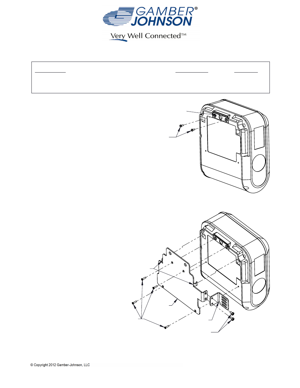
Fig. 1
M2.5 X 6mm
Pan Head Screws
Belt Hook Retainer Plate
Fig. 2
M2.5 X 10mm
Flat Head Screws
Bracket
Strain Relief
6-32 X .25
Pan Head Screws
Bracket Hooks
INSTALLATION INSTRUCTIONS
Product
Revision
Form
If you need assistance or have questions, call Gamber-Johnson at 1-800-456-6868
Printing Spec:
PS-001
BROTHER RUGGED JET PRINTER MOUNT
7160-0425
1. Remove the two M2.5 X 6mm Pan Head Screws
that retain the Belt Hook Retainer Plate. Leave
Belt Hook Retainer Plate in place. Fig. 1
2. Place Bracket on back side of printer such that
Bracket Hooks go into rectangular cavities.
Slide Bracket towards top of printer until
Bracket Hooks engage upper edge of
rectangular cavity. Install the four
M2.5 X 10mm Flat Head Screws.
Fig. 2
3. If desired attach Strain Relief using
two 6-32 X .25 Pan Head Screws.
Fig. 2