Electrical – Flint & Walling Centrifugal Packages - CJ103 User Manual
Page 6
6
95 North Oak Street • Kendallville, IN 46755 • Copyright © 2010. All rights reserved.
ELECTRICAL
Hazardous voltage.
Can shock, burn
or cause death.
Failure to follow
warnings can
cause fatal or
severe shock
hazard or
equipment failure.
Ground motor before connecting
to electrical power supply.
Connect the motor frame to
equipment grounding conductor by
using green screw. Do not connect
green ground wire to any of the motor
leads.
Do not ground to a gas supply
line.
Turn off power to motor before working on electrical
connections.
Supply voltage must be within ±10% of nameplate
voltage. If in doubt consult a licensed electrician.
Use wire size specified in wiring Chart E. If possible,
connect pump to a separate branch circuit with no other
appliances on it. If wiring diagram on motor model plate
differs from diagram shown in figures 8, 9 & 10, follow
diagram on motor.
All wiring should be performed by a qualified electrician
and in accordance with the national and local electric
codes.
WIRING
1. Motor voltages will vary depending upon the
motor horsepower and phase. Refer to the
motor nameplate and the Motor Data Chart
(Chart C) for voltage and electrical data.
Make certain that the power supply
conforms to the electrical specifications of the motor
supplied. Failure to do so may cause premature motor
failure and will void the warranty.
2. To change voltage, remove the rear access
cover, which is held in place with two (2)
screws. For proper electrical connection, refer
to the connection diagram located on the motor
nameplate or figures 8, 9 & 10.
Replace rear access cover before
starting or operating pump. Failure to do so can result
in personal injury.
MOTOR PROTECTION
1. All single phase motors have built in thermal
protection for all voltages. The overload
protects the motor against burnout from
overload of low voltage, high voltage and other
causes. The device is automatic and resets
itself once the temperature has dropped to
a safe point. Frequent tripping of the device
indicates trouble in the motor or power lines
and immediate attention is needed.
Never examine, make wiring changes
or touch the motor before disconnecting the main
electrical supply switch. The thermal device may have
opened the electrical circuit.
2. Three phase motors do not have a built in
thermal protection. It is recommended that a
properly sized magnetic or manual starter (both
with properly sized heaters) be used with all
three phase motors. Install starters following
instructions of the starter manufacturer. See
Figure 11 for magnetic starter wiring diagram.
3. All motors (single and three phase) should be
equipped with a correctly fused disconnect
switch to provide protection. consult local
or national electric codes for proper fuse
protection based on motor data chart (see
Charts C & E).
PRIMING
1. Before starting any centrifugal pump, it is
absolutely necessary that both the casing and
suction pipe be completely filled with liquid.
This priming can be accomplished by any of
the following methods:
2. When the liquid supply level is above the center
line of the pump, it is primed by opening the
suction and discharge valves. The inflowing
liquid will displace the air and fill the suction
IL0182
4
4
5
5
6
6
7
7
8
8
9
9
1
1
2
2
3
3
L
1
L
2
L
3
L
1
L
2
L
3
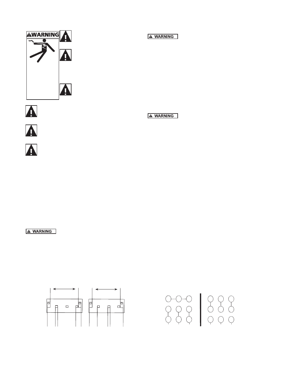
Figure 10 - Wiring Diagram for Three Phase
Low Voltage
230V
High Voltage
460V
IL0180
Figure 9 - Wiring Diagram for Single Phase
1/3-2 HP
L1
A
B
L2
L1
A
B
L2
115 VOLTS
SINGLE PHASE
230 VOLTS
SINGLE PHASE
LINE
LINE
Y
E
L
L
O
W
W
H
I
T
E
G
R
A
Y
R
E
D
T
A
N
Y
E
L
L
O
W
W
H
I
T
E
G
R
A
Y
R
E
D
T
A
N