2 pneumatic installation, Connecting the tubing of the cylinder 8, 4 commissioning – Festo DSNU-…-KP User Manual
Page 7: 5 operation, 1 clamping during operation, 2 moving out of a clamped parking position, 6 maintenance and care
3.2 Pneumatic installation
Connecting the tubing for the clamping cartridge
2/clamping unit5:
1. Remove the mounting screw
9 on
the supply port
1 of the clamping
cartridge
2.
2. Insert a push-in fitting
(M5 DIN 912 or G
Á) into the sup-
ply port
1 of the clamping cart-
ridge
2.
The tightening torque is 0.5 Nm.
Fig. 12
1
2
5
9
Connecting the tubing of the cylinder
8:
• Connect the tubing of the clamping cartridge
2 and the cylinder8 with the direc-
tional control valves intended for this purpose.
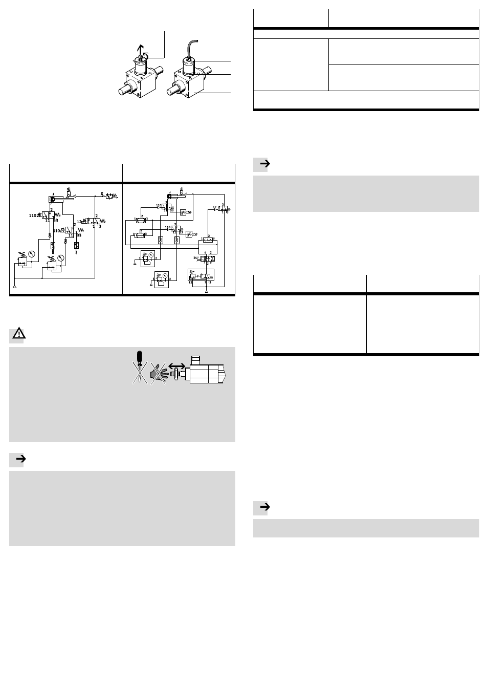
The following shows two examples of control circuits.
Clamping when there is a sudden
pressure failure
Moving to any desired position and
clamping
Fig. 13
4
Commissioning
Warning
Clamping rods can move out suddenly and
unexpectedly, thereby causing injury to
anybody who is in the positioning range.
• Make sure that:
– nobody reaches into the positioning
range of the moveable load
– no objects project into the danger
zone of the moving load
Fig. 14
– the clamping cartridge
2 is logically controlled in a correct manner
– no modifications may be made to the product.
Improper modifications impair the functioning and represent a safety risk.
Note
Clamping in movement sequences (braking) is not permitted. Increased wear
leading to complete failure is possible.
• Make sure that the dynamic holding force is always less than the static holding
force.
Apart from that, the clamping rod can break through.
• Make sure that the cylinder
8 is only pressurised in the park position when the
clamp is released.
Movement against a non-pressurised chamber will create an acceleration
which can damage the cylinder
8.
1. Slowly pressurise the complete system with at least 3 bar.
2. Exhaust the cylinder
8.
3. Completely screw in the adjusting screws on the cylinder
8 for the end-position
cushioning
6.
4. Start a test run as described in table Fig. 15.
5. End the test run.
Clamping cartridge
2/
clamping unit
5
Cylinder with clamping unit
8
Pressurise the supply port
1 on the clamping cartridge2 with 3 to max. 10 bar.
Move the clamping rod
4
in a longitudinal direc-
tion.
Pressurise both ports of the cylinder
8 slowly in
order to prevent danger caused by the piston rod
4
accelerating suddenly.
Adjust the pneumatic end-position cushioning by
means of the adjusting screws (not on cylinders with
elastomer cushioning).
Check the clamping function of the clamping rod
4 by exhausting the supply
port
1.
Fig. 15
5
Operation
The clamping rod
4 can only be moved if the clamping cartridge2 is pressurised
or if the mounting screw
9 is screwed in.
Note
Transverse loadings due to non-aligned guides lead to increased wear.
• Make sure the clamping rod
4 is only loaded in the direction of movement.
• Use a self-aligning rod coupler (
Accessories) in order to avoid transverse
forces.
5.1 Clamping during operation
1. Pressurise the supply port of the park position on the cylinder
8.
2. Exhaust the clamping cartridge
2 and then the cylinder8.
5.2 Moving out of a clamped parking position
Clamping cartridge
2/
clamping unit
5
Cylinder with clamping unit
8
1. Pressurise the supply port
1 on the
clamping cartridge
2 with 3 to
max. 10 bar.
2. Move the clamping rod
4 into the
desired position.
1. Pressurise the piston of the cylin-
der
8 on both sides.
2. Pressurise the supply port
1 on the
clamping cartridge
2 with 3 to
max. 10 bar.
3. Switch the directional control valve
for controlling the cylinder
8.
Fig. 16
5.3 Checking the clamping function of a cylinder with clamping unit
8:
• Check the clamping function on a regular basis and immediately after a sud-
den pressure failure. The piston rod should be located in a park position
when doing this.
Positioning the piston rod:
1. Pressurise the supply ports on the cylinder
8 on both sides.
2. Release the clamping function of the clamping cartridge
2 manually or pneu-
matically.
3. Exhaust one of the supply ports on the cylinder
8 and, in doing so, move the
piston rod
4 to a park position.
Checking to ensure a safe clamping function without an effective load:
1. Pressurise the cylinder
8 on the stroke side chamber so that the piston rod4 is
held securely in the park position.
2. Exhaust the clamping cartridge
2 to clamp the piston rod4.
3. Pressurise the cylinder
8 in the stroke direction.
Note
• Make sure that the maximum holding force of the clamping cartridge
2 is not
exceeded with the cylinder pressure.
The clamping function of the clamping cartridge
2 is fine if the piston rod4 only
moves slightly (
axial play in the chapter “Technical data”).
6
Maintenance and care
Cleaning:
1. Exhaust the cylinder
8 and the clamping cartridge2.
2. Clean the clamping unit and the clamping rod
4 with a soft cloth.
Avoiding unlubricated operation:
3. Lubricate the surface of the clamping rod
4 with a thin layer of grease.
• Use lubricating grease LUB-KC1 SILIKONFREI. The lubricating grease should
only be recognisable by a slight darkening of the surface due to the colour of
the grease.
• Recommendation: Apply the grease with a cloth or soft brush.