2 requirements for use, 3 installation, 1 mechanical installation – Festo DSNU-…-KP User Manual
Page 6: Mounting the clamping rod 4, Mounting the clamping cartridge 2, Mounting the clamping unit 5, Mounting the cylinder with clamping unit 8
2
Requirements for use
Note
Incorrect handling can result in malfunctions.
• Make sure that the specifications contained in this chapter are adhered to at
all times.
This is the only way to ensure correct and safe product behaviour.
Note
Additional measures are necessary if used in safety relevant applications, e.g. in
Europe the standards listed under the EC machinery directive must be observed.
Without additional measures in accordance with statutory minimum require-
ments, the product is not suitable for use in safety-related sections of control
systems.
Note
The clamping cartridge
2 may be damaged if the clamping rod4 is braked.
• Make sure that the following points are observed for clamping:
– The clamp is only released in the pressurised park or end position of the
cylinder.
– The clamping cartridge
2 is only pressurised and exhausted when the
clamping rod
4 has come to a complete standstill.
– There are no dynamic forces.
• Take into consideration the legal regulations applicable for the destination, as
well as:
– regulations and standards
– regulations of the testing organizations and insurers
– national specifications.
• Note the warnings and instructions on the product and in the relevant operating
instructions.
• Remove all transport packaging such as foils, caps and cartons (except for any
plugs in the pneumatic connections).
The material used in the packaging has been specifically chosen for its recyclab-
ility (exception: oil paper = residual waste).
• Observe the local regulations for environmentally friendly waste management of
electronic components.
• Take into account the material specifications
(
Technical data).
• Use the product in its original status, without any unauthorised product modific-
ations.
• Take into consideration the ambient conditions at the location of use.
Corrosive environments (e.g. ozone) will reduce the service life of the product.
• Compare the limit values specified in these operating instructions with your
actual application (e.g. pressures, forces, torques, temperatures, masses,
speeds, etc.).
Operation of the product in compliance with the relevant safety regulations is
contingent on adherence to the load limits.
• Take the tolerance of the tightening torques into account.
Unless otherwise specified, the tolerance is ±20 %.
• Make sure the compressed air is properly prepared (
Technical data).
• Maintain the selected medium for the total service life of the product. Example:
Always use non-lubricated compressed air.
• Slowly pressurise the system as a whole.
There will then be no uncontrolled movements.
For slow start-up pressurisation, use start-up valve type HEL.
3
Installation
3.1 Mechanical installation
• Make sure there is sufficient space for the pneumatic connections as well as
their tubing connections.
Note
If a clamping rod has insufficient surface quality, it may lead to the maximum
holding force
not being reached.
• Make sure the rod has the required quality (
Technical data).
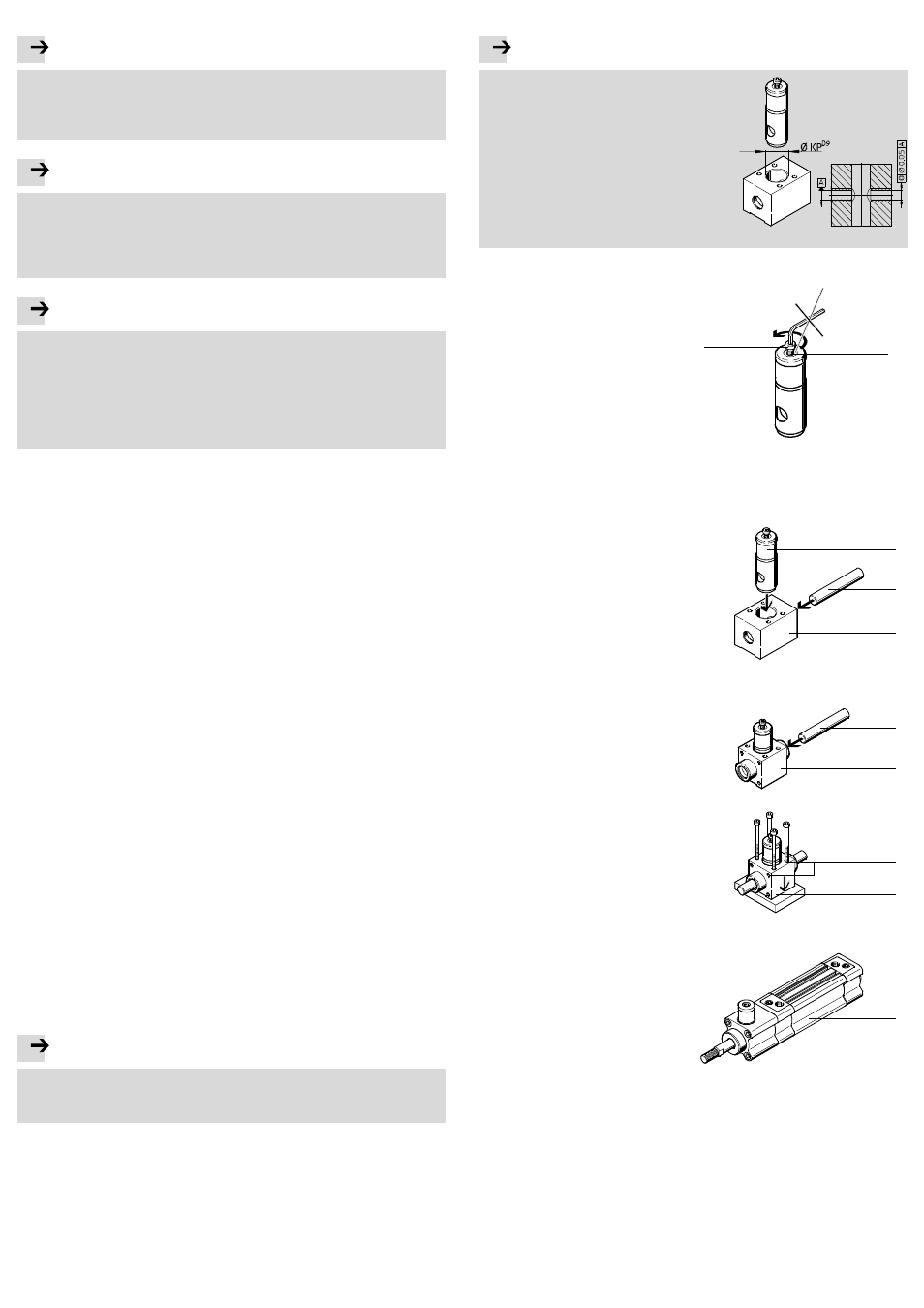
If a housing is used:
Note
There will be increased wear as the holes
are not aligned exactly.
• Make sure of the following:
– the tolerance field of the hole for
holding the clamping cartridge
2
(KP) must correspond to size D9
(DIN ISO 286)
– 2 plain bearings are used on the
housing, whose reference axes A lie
within a coaxial cylinder measuring
0.05 mm in diameter.
Fig. 6
Mounting the clamping rod
4:
1. Manually:
• Leave the pre-assembled mount-
ing screw
9 in the thread of the
supply port
1.
• Only remove it after mounting the
clamping rod
4.
2. Pneumatic:
• Remove the pre-assembled mount-
ing screw
9.
• Pressurise the supply port
1.
Fig. 7
1
9
The clamp is released in both cases and the clamping rod
4 can be mounted.
Mounting the clamping cartridge
2:
1. Push the clamping cartridge
2 from
above into the locating hole of the
housing
5.
2. Push the clamping rod
4 through the
housing
5 and the clamping cart-
ridge
2.
Fig. 8
2
4
5
Mounting the clamping unit
5:
1. Push the clamping rod
4 into the
clamping unit
5.
Fig. 9
4
5
2. Mount the clamping unit
5 at the in-
tended position.
The clamping unit has holes and
threads
3 for mounting purposes.
Fig. 10
3
5
Mounting the cylinder with clamping unit
8:
1. Mount the cylinder
8 on the end face
or use suitable mounting components.
Fig. 11
8
Mounting components for the various cylinders
8 can be found in Festo's ac-
cessories (
www.festo.de\catalogue).