1 function and application, Kp, kpe, adn-…-kp, dnc-…-kp, dsbc-…-c, dsnu-…-kp – Festo DSNU-…-KP User Manual
Page 5
KP, KPE, ADN-…-KP, DNC-…-KP,
DSBC-…-C, DSNU-…-KP
Festo AG & Co. KG
Postfach
D-73726 Esslingen
+49 711 347 0
www.festo.com
Operating instructions
8003373
1205f
Original: de
Clamping cartridge, clamping unit,
cylinder with clamping unit
English
. . . . . . . . . . . . . . . . . . . . . . . . . . . . . . . . . . . . .
Note
Installation and commissioning are to be carried out only by qualified personnel
in accordance with the operating instructions.
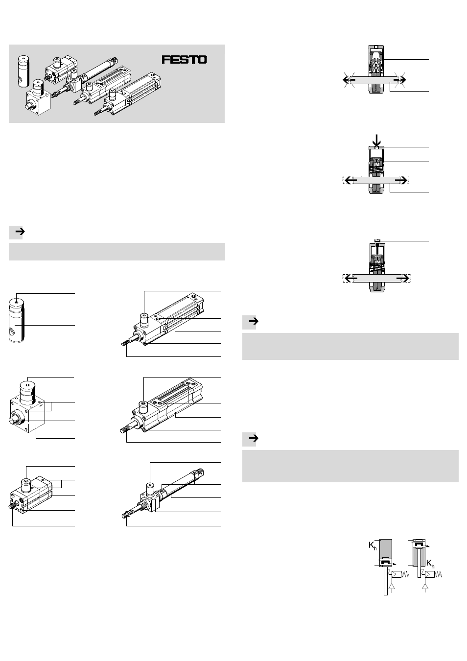
Control sections and connections
KP
1
2
3
4
5
KPE
DSNU-...-KP
4
6
8
DNC-...-KP
4
6
7
ADN-...-KP
6
7
4
DSBC-...-C
4
6
7
2
8
3
2
8
2
2
8
2
1 Thread for
– Supply port or
– Mounting screw
2 Clamping cartridge (KP or C char-
acteristic)
3 Holes and threads for mounting
4 Clamping rod (piston rod or round
material)
5 Clamping unit; housing for holding
the clamping cartridge
2
6 Supply port for cylinder (with ad-
justing screw for end-position
cushioning, if applicable)
7 Thread for mounting
8 Cylinder with clamping unit
Fig. 1
1
Function and application
The clamping cartridge
2 holds the clamping rod 4 (with effective load) firmly in
any position.
Clamping the clamping rod
4
When the clamping cartridge
2 is
exhausted, a spring presses the
clamping jaws apart. As a result of
the clamping jaws being pushed
apart, the jaws are tilted on the
clamping rod
4. The clamping rod
4 is clamped in a friction-locking
manner.
2
4
Fig. 2
Pneumatically releasing the
clamping rod
4
When the clamping cartridge
2 is
pressurised (supply port
1), a pis-
ton presses the clamping jaws to-
gether until the jaws are parallel to
each other. The holes in the clamp-
ing jaws then lie in an axis with the
clamping rod
4. The clamp is re-
leased.
Fig. 3
1
2
4
Manually releasing the clamping
rod
4
• Screw the supplied mounting
screw
9 (M5 DIN 912 or GÁ) in-
to the supply port
1 of the
clamping cartridge
2.
This presses the clamping jaws to-
gether over the piston until the
clamping is loosened.
Fig. 4
9
Note
The clamping cartridge
2 can be damaged when manually releasing the clamp.
• Only screw the mounting screw
9 into the supply port1 until the clamp is
released.
The clamping cartridge
2 is designed for holding a clamping rod4 (in most cases
a piston rod).
The clamping unit is intended for the following applications:
– Holding or clamping the clamping rod
4 in any position.
– Avoiding stroke movements:
– due to fluctuations in the operating pressure
– due to leakage on seals or tubing.
Note
Clamping in movement sequences (braking) is not permitted. Increased wear
leading to complete failure is possible.
• Make sure that the dynamic holding force is always less than the static holding
force.
If a pressure failure occurs (e.g. caused by an emergency switch off ), continued
use is only permitted after a subsequent functional test (
Operation). Except in
the event of sudden pressure failure, clamping may only be undertaken when the
cylinder is in the intermediate or end positions of the cylinder, referred to here as
the parking position.
• Only pressurise a clamped piston rod
4
that is resting in a park position in chamber
(K
h
) on the stroke side.
This is to prevent the piston from moving to
a non-pressurised chamber when clamping
is released.
Fig. 5