Figure 2: wiring diagram cms-e-fr, part 2 – EUCHNER CMS-E-FR User Manual
Page 8
Operating Instructions Safety Switch Evaluation Units CMS-E-FR
EUCHNER GmbH + Co. KG Kohlhammerstraße 16 D-70771 Leinfelden-Echterdingen Tel. +49 711 7597-0 Fax +49 711 753316 [email protected] www.euchner.de
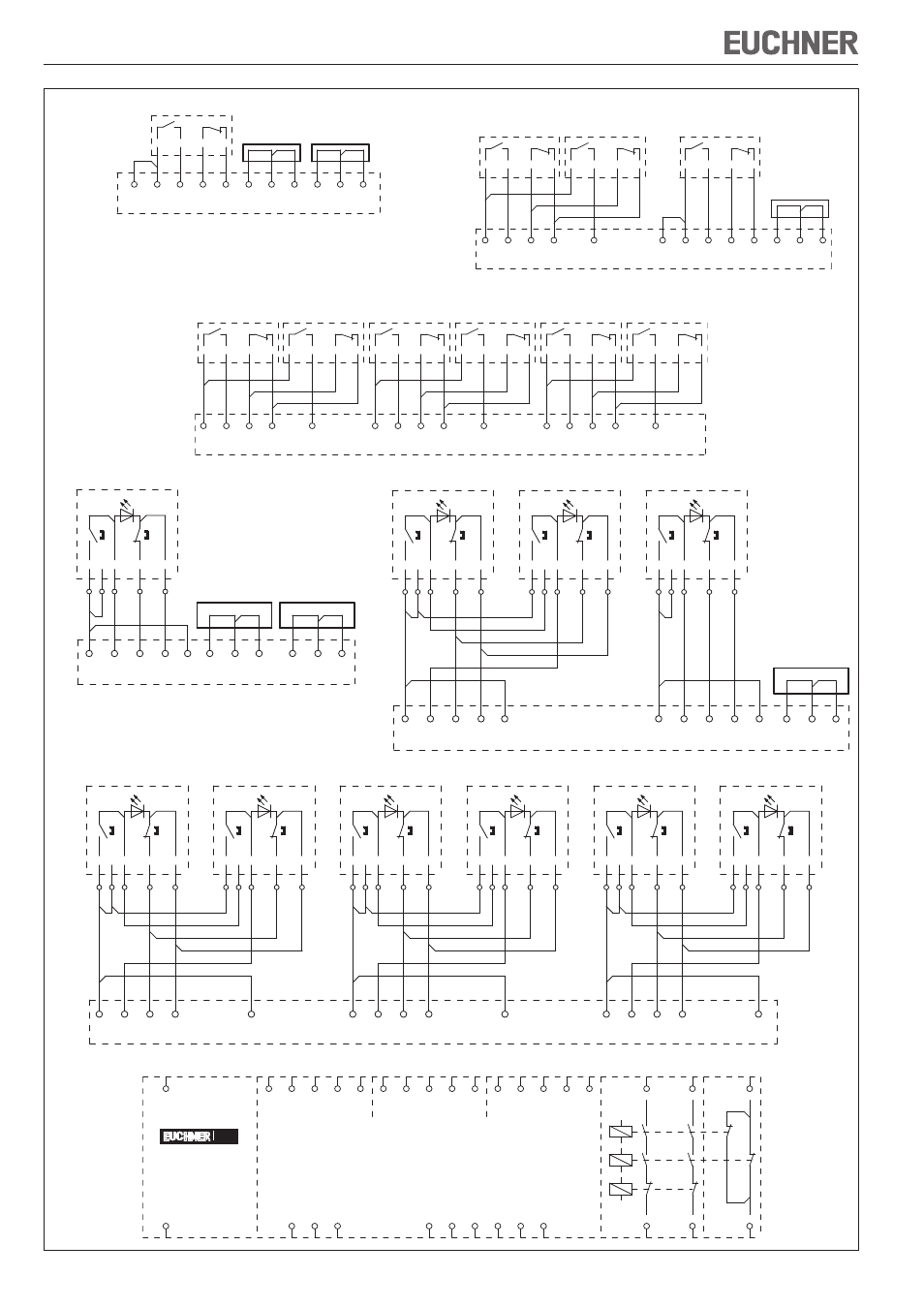
Figure 2: Wiring diagram CMS-E-FR, part 2
The following
applies to all the
illustrations:
Evaluation unit
electrically
isolated, actuator
not in the operat-
ing distance.
Note:
2 3-pin jumpers
are included.
Leseköpfe/read heads
1-2
Hilfs-
kontakte/
auxiliary
contacts
Meldeausgänge/
monitoring outputs
13
14
Rückführkreis/
feedback loop
23
24
Sicherheits-
kontakte/
safety
contacts
CMS
Leseköpfe/read heads
3-4
Leseköpfe/read heads
5-6
H12
H73
H11
0V
A2
UB
A1
H74
31
32
H22
Y1
Y2
Y3
H32
H83
H31
H84
H42
H52
H93
H51
H94
H62
O4
O5
O6
O1
O2
O3
Wiring diagram CMS-E-FR
Wiring diagram for one read head CMS-R-...
H12
H73
H11
H74
H22
H32
H31
H42
H52
H51
H62
BN
WH
BU
BK
Jumper
3-polig/3-pin
Jumper
3-polig/3-pin
1 Lesekopf/1 read head
Wiring diagram for max. 3 read heads CMS-R-...
H62
H12
H73
H11
H74
H22
H32
H31
H42
H52
H51
WH
BN
H83
H84
BN
WH
BN
WH
Jumper
3-polig/3-pin
max. 3 Leseköpfe/3read heads max.
Lesekopf 1/
read head 1
Lesekopf 2/
read head 2
Lesekopf 3/
read head 3
BU
BK
BU
BK
BU
BK
Wiring diagram for one read head CMS-RH-...
H12
H73
H11
H74
H22
Lesekopf/read head
WH
BN
+
BU
BK
-
PK
1 2 3
4
5
1 Lesekopf/1 read head
H32
H31
H42
Jumper
3-polig/3-pin
H52
H51
H62
Jumper
3-polig/3-pin
Wiring diagram for max. 3 read heads CMS-RH-...
H12
H73
H11
H74
H22
H32
H83
H31
H84
H42
Lesekopf 1/read head 1
WH
BN
+
BU
BK
-
PK
Lesekop 2/read head 2
WH
BN
+
BU
BK
-
PK
Lesekopf 3/read head 3
WH
BN
+
BU
BK
-
PK
1 2 3
4
5
6 7 8
9
10
11 12 13
14
15
max. 3 Leseköpfe/3 read heads max.
H52
H51
H62
Jumper
3-polig/3-pin
Wiring diagram for max. 6 read heads CMS-R-...
BK
BU
BK
BU
BK
BU
BK
BU
BK
H12
H73
H11
H22
WH
BN
BN
WH
H74
H32
H83
H31
H42
WH
BN
BN
WH
H84
H52
H93
H51
H62
WH
BN
BN
WH
H94
max. 6 Leseköpfe/6 read heads max.
Lesekopf 1/
read head 1
Lesekopf 2/
read head 2
Lesekopf 3/
read head 3
Lesekopf 4/
read head 4
Lesekopf 5/
read head 5
Lesekopf 6/
read head 6
BU
BK
BU
Wiring diagram for max. 6 read heads CMS-RH-...
H12
H73
H11
H74
H22
H32
H83
H31
H84
H42
H52
H93
H51
H94
H62
Lesekopf 1/read head 1
WH
BN
+
BU
BK
-
PK
Lesekopf 2/read head 2
WH
BN
+
BU
BK
-
PK
Lesekopf 3/read head 3
WH
BN
+
BU
BK
-
PK
Lesekopf 4/read head 4
WH
BN
+
BU
BK
-
PK
Lesekopf 5/read head 5
WH
BN
+
BU
BK
-
PK
Lesekopf 6/read head 6
WH
BN
+
BU
BK
-
PK
-X6
1 2 3
4
5
6 7 8
9
10
11 12 13
14
15
16 17 18
19
20
21 22 23
24
25
26 27 28
29
30
max. 6 Leseköpfe/6 read heads max.