EUCHNER TXxxx User Manual
Page 9
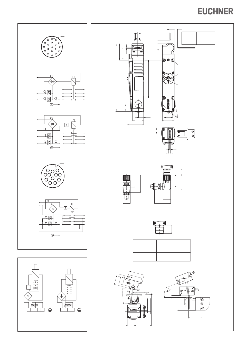
Mode d’emploi pour les interrupteurs de sécurité TX...
Languette
Prof. d'insert. s
Standard
32 + 1
Surcourse
32 + 8
30
42
GN
RD
s
s
21
,5
8,5
4,5
58
,5
46
13
4
18,8
39
59
25
,5
24
0
4,
5
G
22
75
60
65
80
∅26
58
∅26
29
Figure 5a :
TX...M
G = M20x1,5
TX...N
G = ½“ NPT
Figure 5b :
TX...RC18
Figure 5c :
TX...BH12
Profondeur d'insertion
Pr
of
on
de
ur
d'
in
se
rti
on
pour M5 > 45 mm
ISO 1207 (DIN 84),
ISO 4762 (DIN 912)
Déverrouillage de secours
Vis de protection
co
nn
ec
té
e
co
nn
ec
té
e
PE/12
19
GN
RD
9
11
5
12/14
11/13
21
22
10
13
7
8
14
34
42
33
41
15
16
2
3
4
6
1
TX1...RC18
TX2...RC18
PE/12
19
GN
RD
9
11
5
12/14
11/13
21
22
10
13
7
8
14
34
42
33
41
15
16
2
3
5
6
1
17
4
TX3...RC18
PE/9
12
GN
RD
1
11
12/14
11/13
21
22
2
3
4
6
34
42
33
41
2
3
5
5
1
10
4
TX3...BH12
1
8
9
2
3
4
5
6
7
11
12
10
Affectation
des broches
connecteur BH12
Avancé, avec
ressort de
protection
Affectation
des broches
connecteur RC18
13
14
16
17
1
2
3
4
5
7
8
9
10
11
6
15
19
18
12
Avancé, avec ressort
de protection
Figure 3 : Affectation des broches (connecteurs)
Figure 4 : Connexions
TX1/TX2
TX...110/230
TX3...024
L D
G
L D
D
V
B
1 2
3 4
U
E
N
E
R
0
1.
2.
3.
4.
1.
2.
3.
4.
&
1 2
3 4
5
U
LED
GN
LED
RD
U
0V
B
S
1.
2.
3.
4.
1.
2.
3.
4.
Figure 5 : Dimensions TX..., profondeur d’insertion et rayons d'entrée
Ø
40
16
20
50
40
28
14
61
13,5
21,5
8
R > 10
0
7
21
30
45
32+8
5,5
Langauette X-OU-N
Languette X-LR-N
8,
8
21,5
Ø 5,5
40
R>100
*=R
5,
1
51
4
23
29
50
43,15
<41,65>
30
14
32 +8
32 +8
5,1
46,3
Type languette
Rayon porte min. [mm]
LANGUETTE X-GQ
300
LANGUETTE X-WQ
LANGUETTE X-GNQ
440
LANGUETTE X-WNQ