Operating instructions safety switches tx – EUCHNER TXxxx User Manual
Page 4
Operating Instructions Safety Switches TX...
EUCHNER GmbH + Co. KG Kohlhammerstraße 16 D-70771 Leinfelden-Echterdingen Tel. +49/711/75 97-0 Fax +49/711/75 33 16 www.euchner.de [email protected]
Correct Use
Safety switches series TX are electromagnetic inter-
lock devices with guard locking.
In combination with a separating safety guard and the
machine control, this safety component prevents the
safety guard from being opened while a dangerous
machine movement is being performed.
For the control system, this means that
starting commands which cause hazardous situ-
ations must become active only when the safety
guard is in protective position and the guard locking
is in locked position.
The locked position of the guard locking must be
released only when the hazardous situation is no
longer present.
Before safety switches are used, a risk assessment
must be performed on the machine in accordance
with
EN ISO 13849-1, Safety of machinery. Safety re-
lated parts of control systems. General principles
for design
EN ISO 12100, Safety of machinery - General
principles for design - Risk assessment and risk
reduction
IEC 62061, Safety of machinery – Functional safety
of safety-related electrical, electronic and program-
mable electronic control systems.
Correct use includes compliance with the relevant
requirements for installation and operation, in par-
ticular
EN ISO 13849-1, Safety of machinery. Safety re-
lated parts of control systems. General principles
for design
EN 1088, Safety of machinery. Interlocking devices
associated with guards. Principles for design and
selection
EN 60204-1, Safety of machinery. Electrical equip-
ment of machines. General requirements.
Important:
The user is responsible for safe integration of the
device in a safe overall system. For this purpose
the overall system must be validated, e.g. in ac-
cordance with EN ISO 13849-2.
If the simplified method according to section 6.3
EN ISO 13849-1:2008 is used for validation, the
Performance Level (PL) may be reduced if several
devices are connected one after the other.
If a product data sheet is included with the product,
the information on the data sheet applies in case of
discrepancies with the operating instructions.
Safety Precautions
Safety switches perform a personal protection func-
tion. Incorrect installation or tampering can lead to
severe injuries to personnel.
Safety components must not be bypassed
(bridging of contacts), turned away, removed
or otherwise rendered ineffective.
On this topic pay attention in particular to the
measures for reducing the possibility of bypassing
according to EN 1088:1995.A2:2008, sec. 5.7.
The switching operation may only be triggered
by actuators specially provided for this purpose
which are permanently connected to the protec-
tive guard.
Mounting, electrical connection and setup only
by authorized personnel.
Function
The safety switch permits the locking of movable
safety guards.
In the switch head there is a rotating cam that is
blocked/released by the guard locking pin. The guard
locking pin is moved on the insertion / removal of
the actuator and on the activation / deactivation of
the guard locking. During this process the switching
contacts are actuated.
If the cam is blocked, the actuator cannot be pulled
out of the switch head
Æ
guard locking active.
Versions TX1 and TX3
(Guard locking by spring force)
The guard locking pin is held in the locked position
by spring force and released by electromagnetic
actuation. The guard locking functions in accordance
with the closed-circuit current principle. The safety
guard cannot be opened immediately in the event of
interruption of the solenoid power supply.
Version TX2
(Guard locking by solenoid force)
This type must be used only in special cases
after strict assessment of the accident risk!
The safety guard can be opened immediately in
the event of interruption of the solenoid power
supply!
The guard locking pin is held in locked position by
electromagnetic force and released by spring force.
The guard locking operates in accordance with the
open-circuit current principle.
Closing safety guard and activating guard
locking.
The guard locking pin is released by insertion of the
actuator into the safety switch.
TX1 and TX3: The guard locking pin is moved to
locked position by spring force.
TX2: The guard locking pin is moved to locked posi-
tion when the solenoid operating voltage is applied.
The safety contacts are closed.
Deactivating guard locking, opening safety
guard
TX1 and TX3...110/230: The guard locking pin
releases the cam when the solenoid operating volt-
age is applied.
For switching function see Figure 2 column 2 Door
closed and not locked
The actuator can be removed.
TX3...024: The guard locking pin releases the cam
when the solenoid operating voltage is applied when
the control voltage is present.
For switching function see Figure 2 column 2 Door
closed and not locked
The actuator can be removed.
TX2: The guard locking pin releases the cam when
the solenoid operating voltage is switched off.
For switching function see Figure 2 column 2 Door
closed and not locked
The actuator can be removed.
Door monitoring contact
On the removal of the actuator, the door monitoring
contact switches and signals that the safety guard is
open (see Figure 2 column 3, Door open).
Mechanical Release
In the event of malfunctions, the guard locking can be
deactivated using the mechanical release, irrespec-
tive of the state of the solenoid (see Figure 5).
Unscrew locking screw
Using a screwdriver, turn the mechanical release by
around 180° in the direction of the arrow
The locking screw must be returned to its original
position and sealed after use (for example with seal-
ing lacquer).
Installation
Safety switches and actuators must not be used
as an end stop.
Mount the safety switch only in assembled condi-
tion!
Assemble the safety switch so that
access to the switch is difficult for operating person-
nel when the safety guard is open
it is possible to operate the mechanical release and
check and replace the safety switch.
Fit an additional end stop for the movable part of
the safety guard.
Insert the actuator in the actuating head.
Mount the safety switch positively.
Permanently connect the actuator to the safety
guard so that it cannot be detached, e.g. using
the enclosed non-removable screws, rivets or
welding.
Changing the Actuating Direction
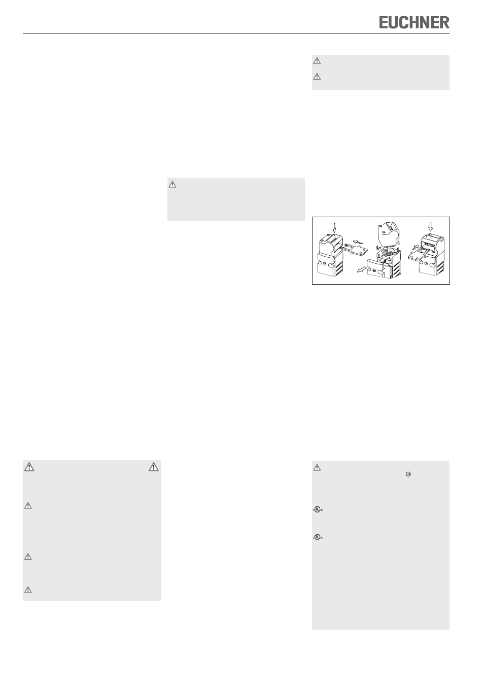
Figure 1: Changing the actuating direction
Unscrew and open switch cover.
Remove actuating head from the switch by turning
and refit in the required position (bayonet fasten-
ing).
Fit locking pins supplied for protection against
twisting.
Close the cover and screw in position.
Cover the unused actuating slot with the enclosed
slot covers.
Protection Against Environmental Influ-
ences
A lasting and correct safety function requires that
the actuating head must be protected against the
penetration of foreign bodies such as swarf, sand,
blasting shot, etc.
Cover the actuating slot, the actuator and the rating
plate during painting work!
Electrical Connection
Only switching contacts marked with the posi-
tively driven NC contact symbol are to be used
for the safety circuit.
For TX without plug connector:
For use and applications as per the requirements of
, a rigid copper wire 60/75° is to be used.
For TX with plug connector:
For use and applications as per the requirements of
, a class 2 power supply or a class 2 transformer
according to UL1310 or UL1585 must be used.
Connection cables for safety switches installed at the
place of use must be separated from all moving and
permanently installed cables and un-insulated active
elements of other parts of the system which operate
at a voltage of over 150 V. A constant clearance of
50.8 mm must be maintained. This does not apply if
the moving cables are equipped with suitable insula-
tion materials which possess an identical or higher
dielectric strength compared to the other relevant
parts of the system.
A