Operating instructions safety switches tx, Inspection and service, Declaration of conformity – EUCHNER TXxxx User Manual
Page 5: Functional check, Technical data
Operating Instructions Safety Switches TX...
Inspection and Service
If damage or wear is found, the complete switch
and actuator assembly must be replaced.
Replacement of individual parts or assemblies
is not permitted!
No servicing is required, but regular inspection
of the following is necessary to ensure trouble-free
long-term operation:
correct switching function
secure mounting of components
dirt and wear
sealing of cable entry
loose cable connections or plug connectors.
Safety switches must be exchanged completely after
1 million switching operations.
Note: The year of manufacture can be seen in the
bottom, right corner of the rating plate.
Exclusion of Liability under the Following
Conditions:
incorrect use
non-compliance with safety regulations
installation and electrical connection not performed
by authorized personnel
failure to perform functional checks.
Declaration of Conformity
The manufacturer named below herewith declares that
the product fulfills the provisions of the directive(s)
listed below and that the related standards have
been applied.
EUCHNER GmbH + Co. KG
Kohlhammerstraße 16
70771 Leinfelden-Echterdingen, Germany
Directives applied:
Machinery directive 2006/42/EC
Standards applied:
EN 60947-5-1:2004 + Cor.:2005 + A1:2009
EN 1088:1995+A2:2008
Leinfelden, July 2010
Dipl.-Ing. Michael Euchner
Director
Duc Binh Nguyen
Authorized representative empowered to draw up
documentation
The signed EC declaration of conformity is included
with the product.
Su
bj
ec
t t
o
te
ch
ni
ca
l m
od
ifi
ca
tio
ns
; n
o
re
sp
on
si
bi
lit
y
is
a
cc
ep
te
d
fo
r t
he
a
cc
ur
ac
y
of
th
is
in
fo
rm
at
io
n.
©
E
UC
HN
ER
G
m
bH
+
C
o.
K
G
07
97
77
-0
5-
06
/1
1
(tr
an
sl
at
io
n
of
th
e
or
ig
in
al
o
pe
ra
tin
g
in
st
ru
ct
io
ns
)
The solenoid operating voltage, the LED operating
voltage and the control voltage (only TX3...024) for
the interlocking solenoid must comply with the infor-
mation on the rating plate (e.g. U
B
= AC/DC 24 V).
Solenoid operating voltage and control voltage can be
jumpered if a current of 2 A can be supplied when the
solenoid is switched on for T
IMP
= 250 ms.
Version TX...M/N (cable entry)
Unscrew locking screw for the required insertion
opening.
Fit the cable gland with the appropriate degree of
protection.
Important: To achieve the specified degree of pro-
tection, use a cable gland from EUCHNER (order. no.
110 132, 110 133 or 110 134).
For pin assignment see Figure 4.
Tighten the screws with a torque of 0.5 Nm.
Check that the cable entry is sealed.
Close the cover and screw in position.
Version TX..RC18/BH12 (plug connector)
For pin assignment see Figure 3.
Functional Check
Warning! Danger of fatal injury as a result of faults
in installation and functional check.
Before carrying out the functional check, make
sure that there are no persons in the danger
area. Observe the valid accident prevention
regulations.
After installation and any fault, the safety function
must be fully checked. Proceed as follows:
Mechanical function test
The actuator must slide easily into the actuating
head. Close the safety guard several times to check
the function.
Electrical function test
1. Switch on operating voltage.
2. Close all safety guards.
In the case of guard locking by solenoid force,
Æ
activate guard locking.
The machine must not start automatically.
It must not be possible to open the safety guard.
3. Enable operation in the control system.
It must not be possible to deactivate the guard
locking as long as operation is enabled.
4. Disable operation in the control system and
deactivate guard locking.
The safety guard must remain locked until there is
no longer any risk of injury.
It must not be possible to start the machine as long
as the guard locking is deactivated.
Repeat steps 2 - 4 for each safety guard.
Technical Data
Parameter
Value
Housing material
Die-cast alloy, cathodically
dipped
Degree of protection according
to IEC 60529
with cable gland
with plug connector
IP 67
IP 65
Mech. operating cycles
>1x10
6
Ambient temperature
-20 ... +80°C℉
Degree of contamination (exter-
nal, according to EN 60947)
3 (industrial)
Installation position
any, preferably actuator head
down
Approach speed, max.
20 m/min
Switching principle
Slow-action switching contact
Contact material
Silver alloy, gold flashed
Connection type to switching
element
Screw terminals
Connection type to printed
circuit board
Cage-pull clamps
Conductor cross-section
(rigid/flexible)
0,34 ... 1.5 mm²
Rated insulation voltage
with cable gland
with plug connector
U
i
= 250 V
U
i
= 50 V
Rated impulse withstand voltage
with cable gland
with plug connector
U
imp
= 2.5 kV
U
imp
= 1.5 kV
Rated short-circuit current
100 A
Utilization category of the switching element according to
EN 60947-5-1
AC-15
DC-13
4 A 230 V
4 A 24 V
Switching voltage, min.
12 V
Switching current, min., at 24 V 1 mA
Short circuit protection
according to IEC 60269-1
4 A gG
Solenoid operating voltage U
B
/
solenoid power consumption
(TX3...024:
I
B
= 2 A for T
IMP
= 250 ms)
AC/DC 24 V
8 W
AC/DC 110 V 10 W
AC/DC 230 V 11 W
Duty cycle
100 %
Switching frequency max.
for TX3
45 min
-1
Control voltage U
S
for TX3...024 AC/DC 24 V
Actuating force
35 N
Extraction force
35 N
Retention force
20 N
Locking force F
max
1,700 N
Locking force F
Zh
in accordance
with test principles GS-ET-19
(F
Zh
=
F
max
) = 1,300 N
1,3
Actuation frequency
1200/h
Reliability figures according to EN ISO 13849-1
B
10d
6 x 10
6
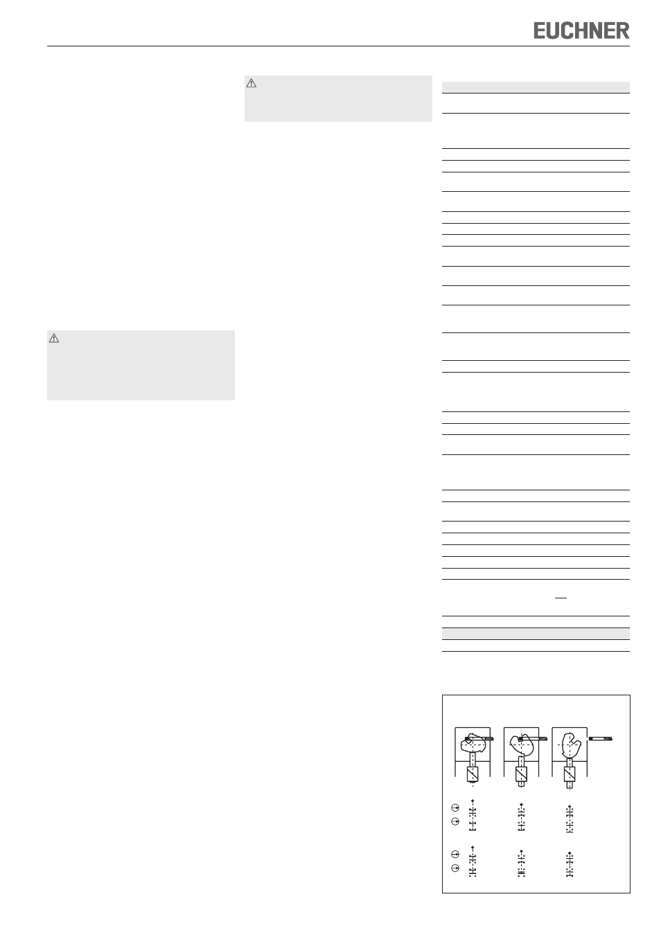
TX.B-...
TX.C-...
41
33
13
21
21
11
33
41
42
34
22
14
12
22
34
42
41
33
13
21
21
11
33
41
42
34
22
14
12
22
34
42
41
33
13
21
21
11
33
41
42
34
22
14
12
22
34
42
Door closed
Door closed,
and locked
not locked
Door open
Figure 2: Switching elements and switching functions