Operating instructions safety switches nz.h/p – EUCHNER NZ Safety switch User Manual
Page 5
Operating Instructions Safety Switches NZ.H/P
EUCHNER GmbH + Co. KG Kohlhammerstraße 16 D-70771 Leinfelden-Echterdingen Tel. +49/711/75 97-0 Fax +49/711/75 33 16 www.euchner.de [email protected]
Subject to technical modifications; no r
e
sponsibility is accepted for the accuracy of this information. © EUCHNER GmbH + Co. KG
074550-09-12/10 (translation of the original operating instructions)
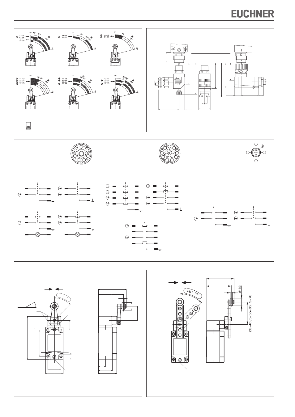
Plug connector SR11
Pin assignment male socket
(Top view of switch mounted
connector)
Terminal assignment for switching elements
SK2121H
SK2131H
7
5
3
1
8
6
4
2
41
33
21
11
42
34
22
12
7
5
3
1
8
6
4
2
41
33
21
13
42
34
22
14
Figure 6b
Figure 6: Switching element and connector assignment
Plug connector SR6
Pin assignment male socket
(Top view of switch mounted
connector)
Terminal assignment for switching elements
ES 511/ES 528H
ES 538H
with LED indicator
3
1
4
2
13
21
14
22
5
6
3
1
4
2
13
21
14
22
3
1
4
2
11
21
12
22
5
6
3
1
4
2
11
21
12
22
Figure 6a
Plug connector SVM5
(M12, 5-pin)
Pin assignment male socket
(Top view of switch mounted
connector)
Figure 6c
Terminal assignment for switching elements
ES 511/ES 528H
ES 538H
3
1
4
2
13
21
14
22
3
1
4
2
11
21
12
22
7
5
3
1
8
6
4
2
41
31
21
11
42
32
22
12
SK3131H
4
3
1
2
ES511
ES528H
ES538H
SK2131H
SK3131H
A
B
C
A
B
C
A
B
C
A
B
C
A
A
B
C
SK2121H
A
C
B
Figure 4: Travel diagrams
Contacts
open
closed
Figure 5: Dimension drawing NZ2... with plug connector
SR11WF
SR6WF
55
13,5
50
75
40
56
40
11
15,2
SR6EF/SR11EF
∅ 28
60
80
16
26
Plug
Cable diameter
connectors
[mm]
SR6
7.0 - 9.0
SR11
8.0 - 10.0
Inser
te
d
Inser
te
d
Inser
te
d
A
Operating point
B
End position
C
Reset point
Figure 8: Dimension drawing NZ1P.. with cable entry
Figure 7: Dimension drawing NZ1H.. with cable entry
Approach directions
HB = Plastic roller (dimension X=6 mm)
HS = Steel roller (dimension X=5 mm)
PB = Plastic roller (dimension X=6 mm)
PS = Steel roller (dimension X=5 mm)
3
0
m
a
x
.
45
+5
40
+1
30
±0,1
74
100
22
7,3
60
±0,1
5,3
5,3
X
64
56
32
∅
18
42
16
32
M=1,2 Nm
M=1,2 Nm
M20x1,5
Dog
Approach directions
M = 1,2 Nm
66
59
X
M20x1,5