Operating instructions safety switches nz.h/p – EUCHNER NZ Safety switch User Manual
Page 4
Operating Instructions Safety Switches NZ.H/P
Correct use
Safety switches of type series NZ are used in control systems
that perform safety functions, e.g. for safety guards or as
position encoders.
The safety switches are positively driven auxiliary power swit-
ches and comply with the requirements as per IEC 60947-5-1
/ EN 60947-5-1 annex K.
In combination with a separating safety guard, this safety
device prevents dangerous machine movements from
occurring while the safety guard is open. A stop command is
triggered if the safety guard is opened during the dangerous
machine function.
Before safety switches are used, a risk assessment must be
performed on the machine in accordance with
EN ISO 13849-1, Safety of machinery. Safety related parts
of control systems. General principles for design
EN ISO 14121, Safety of machinery. Risk assessment.
Principles.
Correct use includes compliance with the relevant
requirements for installation and operation, particularly
EN ISO 13849-1, Safety of machinery. Safety related parts
of control systems. General principles for design
EN 1088, Safety of machinery. Interlocking devices
associated with guards. Principles for design and selection
EN 60 204-1, Electrical equipment of machines
Important:
The user is responsible for safe integration of the device in a
safe overall system. For this purpose, the overall system must
be validated, e.g. in accordance with EN ISO 13849-2.
If the simplified method according to section 6.3 EN ISO
13849:2008-12 is used for validation, the Performance
Level (PL) may be reduced if several devices are connected
one after the other.
If a product data sheet is included with the product, the
information on the data sheet applies in case of
discrepancies with the operating instructions.
Safety precautions
Safety switches fulfill a personal protection function. Incorrect
installation or tampering can lead to severe injuries to
personnel.
Safety components must not be bypassed (bridging of
contacts), turned away, removed or otherwise rendered
ineffective.
On this topic pay attention in particular to the measures
for reducing the possibility of bypassing according to
EN 1088:1995.A2:2008, sec. 5.7.
Safety switches and trip dogs must be arranged such
that they are adequately secured against movement.
To meet these requirements:
The fixings must be reliable and must also require the use
of a tool to undo them.
The use of slots must be limited to the initial adjustment.
Precautions must be taken to ensure that there is no
movement after adjustment (e.g. using bolts or dowel
pins).
Mounting, electrical connection and setup only by
authorized personnel.
Function
See travel diagram.
Mounting
The safety switches must not be used as a mechanical
end stop.
The actuator (lever arm) must be positively mounted to the
actuating shaft. The square drive on the actuator and
actuating shaft must engage with each other (see Figure 1).
To ensure correct operation, the trip dogs must be fitted
so that the actuator is deflected by at least an angle of
45°
+5°
(achievement of the stipulated contact opening,
see Figure 7 and 8).
Safety switches must be attached and, if necessary,
protected in such a way that predictable damage can be
avoided.
It must be ensured that safety switches are accessible
for maintenance and function tests.
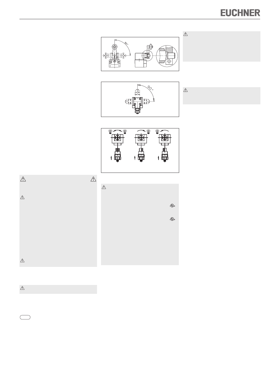
Adjustment options
Vertical actuator adjustment 4 x 90° (positive mounting)
Fig. 1: Vertical actuator adjustment
Horizontal adjustment 4 x 90°
Fig. 2: Horizontal adjustment
Switching direction change with lever arm actuation
Fig. 3: Changing the switching direction
Electrical connection
When choosing the insulation material and wire for the
connections, pay attention to the over-temperature in
the housing (depending on the operating conditions)!
For NZ1:
For use and applications as per the requirements of
, a
rigid copper wire 60/75 °C is to be used.
For NZ2:
For use and applications as per the requirements of
, a
class 2 power supply or a class 2 transformer according to
UL1310 or UL1585 must be used.
Connection cables for safety switches installed at the place
of use must be separated from all moving and permanently
installed cables and un-insulated active elements of other
parts of the system which operate at a voltage of over 150
V. A constant clearance of 50.8 mm must be maintained.
This does not apply if the moving cables are equipped with
suitable insulation materials which possess an identical or
higher dielectric strength compared to the other relevant
parts of the system.
Version NZ1... (cable entry)
Fit cable gland M20 x 1.5 with appropriate degree of
protection.
Conductor cross-section 0.34 ... 1.5 mm².
For terminal assignment see Figure 6.
Tighten screws for connections to 0.5 Nm (1 Nm on
ES511).
Check that the cable entry is sealed.
Close switch cover and tighten screws to 1.2 Nm.
Version NZ2... (plug connector SR6)
Conductor cross-section 0.5 ... 1.5 mm².
For connector assignment see Figure 6a.
Version NZ2... (plug connector SR11)
Conductor cross-section 0.5 mm².
For connector assignment see Figure 6b.
Version NZ2... (plug connector M12/SVM5)
Conductor cross-section 0.34 mm².
For connector assignment see Figure 6c.
Functional check
When the safety guard is open, the safety switch must
be actuated in any safety guard position (overrun
protection).
In safety circuits, check the safety function.
The machine must stop when the safety switch is actuated.
The machine must not start when the safety switch is
actuated.
Mechanical function test
Check the actuating element for freedom of movement.
Electrical function test
Actuate switch and check the switching function.
Inspection and service
If damage or wear is found, the complete switch and
actuator assembly must be replaced.
Replacement of individual parts or assemblies is not
permitted!
No servicing is required, but regular inspection of the
following is necessary to ensure trouble-free long-term
operation:
correct switching function
secure mounting of components
dirt and wear
sealing of cable entry
loose cable connections or plug connectors.
Note:The year of manufacture can be seen in the bottom,
right corner of the rating plate.
Exclusion of liability under the following
circumstances
incorrect use
non-compliance with safety regulations
installation and electrical connection not performed by
authorized personnel.
failure to perform functional checks.
EC declaration of conformity
The manufacturer named below herewith declares that the
product fulfills the provisions of the directive(s) listed below
and that the related standards have been applied.
EUCHNER GmbH + Co. KG
Kohlhammerstraße 16
70771 Leinfelden-Echterdingen, Germany
Directives applied:
Machinery directive 2006/42/EC
Standards applied:
EN 60947-5-1:2004 + Cor.:2005 + A1:2009
EN 1088:1995+A2:2008
Leinfelden, July 2010
Dipl.-Ing. Michael Euchner
Director
Duc Binh Nguyen
Authorized representative empowered to draw up
documentation
The signed EC declaration of conformity is included with
the product.
Left / right
Right switching
Left switching
switching
(standard position)