Data terminations, Connect beacon wires, N o t e – ETC Sensor CE Rack (ESR) ECEM to CEM3 Retrofit User Manual
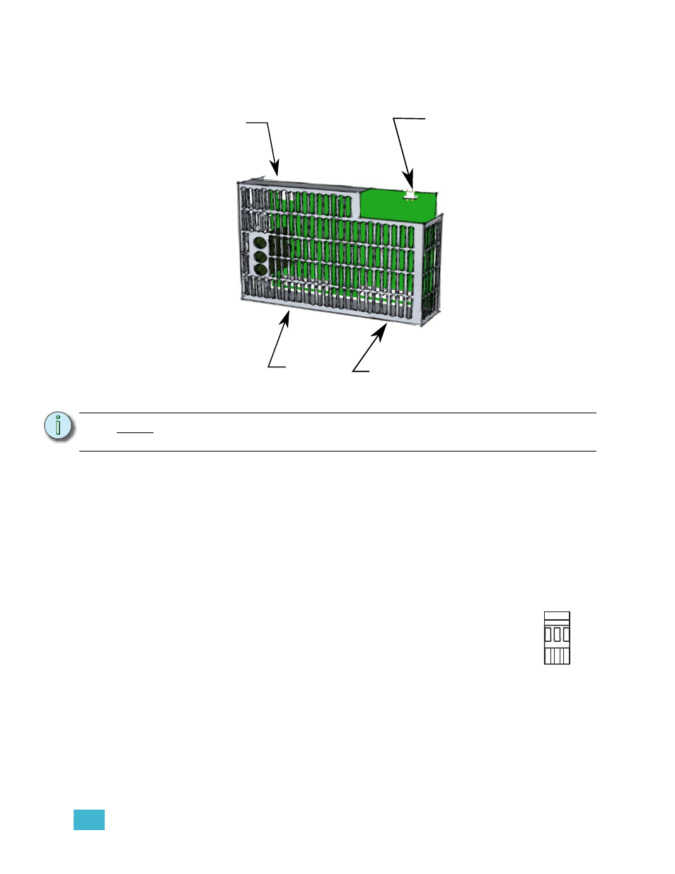
Page 9: Power in power out fan output control input
2
The Retrofit
7
Step 17: Disconnect the three Molex power connectors and the small relay control
connector from the fan filter relay board.
Step 18: By pulling the relay control wires through, you should be able to remove them
from the rack. You will be left with three beacon wires at the backplane location.
Step 19: Remove the harness that ran from the fan filter relay board to the ECEM power
connector, carefully clipping cable ties as required.
Data Terminations
Connect beacon wires
Step 1:
Strip 6mm (1/4 inch) of insulation from the end of the remaining red,
blue and black wires (the beacon wires)
Step 2:
Connect the three wires to the 3 pin phoenix connector supplied in
the new backplane, in the order shown at right.
N o t e :
The fan filter relay board is not used after upgrade. It can be removed from the
rack if desired, or left in place.
Power In
Power Out
Fan Output
Control Input
1
2
3
J16
Beacon
Pin-out
Bl
ack
Bl
ue
Red