ETC Sensor CE Rack (ESR) ECEM to CEM3 Retrofit User Manual
Page 8
6
CEM3 Sensor ESR Rack Retrofit Manual
through the standoffs on the side of the backplane into the rack metal
Step 5:
Pull backplane towards the front of the rack to free the backplane side tabs
Step 6:
Bend the right side of the backplane metal toward the centre (away from the side
of the rack)
Step 7:
Slide backplane metal forward to remove it from the rack, cut the earth lead to
the chassis and discard the wire.
Step 8:
Mark the connectors on the grey dimmer output ribbon cables (using permanent
marker).
•
The connectors are designated 1-24, 25-48, 49-72 and 73-96 (depending on
the size of the rack, you may have fewer ribbon cables).
•
The connector can be identified by referring to the white printing on the old
backplane PCB
Step 9:
Once all the ribbon cables are marked, disconnect them.
Step 10: If fitted, remove the ferrite toroids from the cables and discard.
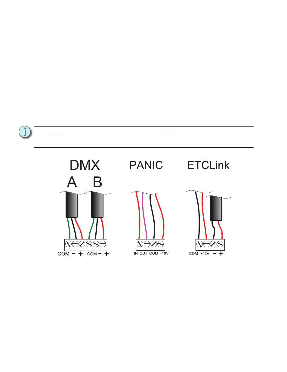
Step 11: Document and remove the input data wires (ETCLink, DMXA, DMXB and Panic).
Step 12: Disconnect the 5 pin beacon & fan relay control connector from the backplane
PCB
Step 13: If in a dual tracking system, disconnect the 3 pin local switch connector from the
backplane
Step 14: Remove the backplane PCB and return the backplane to ETC Technical
Step 15: Cut the 5 pin header from the beacon cable, as close as possible to the connector
that was connected to the backplane PCB.
Step 16: Locate the fan filter relay board for your rack. The fan filter relay board is located
behind the ECEM attached to the back of the rack for ESR24,36 and 48 racks.
•
The fan filter relay board is located at the top of the rack in ESR12 racks
N o t e :
Be sure to note and label the wires before disconnecting them from the terminal
strips. You will need to connect these wires to the new backplane in the correct
order later.