The retrofit, Preparation, Remove the old – ETC Sensor CE Rack (ESR) ECEM to CEM3 Retrofit User Manual
Page 7
2
The Retrofit
5
S e c t i o n 2
The Retrofit
Preparation
Step 1:
Use Sensor Configuration Editor and a SLTA if you wish to download and save
the current Sensor configuration out of the racks for later reference. For
information on this process contact ETC Technical Services (see
Step 2:
Turn off main power to the rack(s).
Step 3:
Remove the eight dimmer modules above the ECEM (if retrofitting an ESR36 or
48 rack, remove the eight modules below the ECEM as well). Note and document
the modules’ order/positioning in the rack for proper insertion and configuration
later.
Step 4:
Use a digital voltmeter to VERIFY that power is off by checking voltages for all
combinations between the phase bars, neutral and earth.
Step 5:
Remove the ECEM(s) from the rack.
Remove the Old
Step 1:
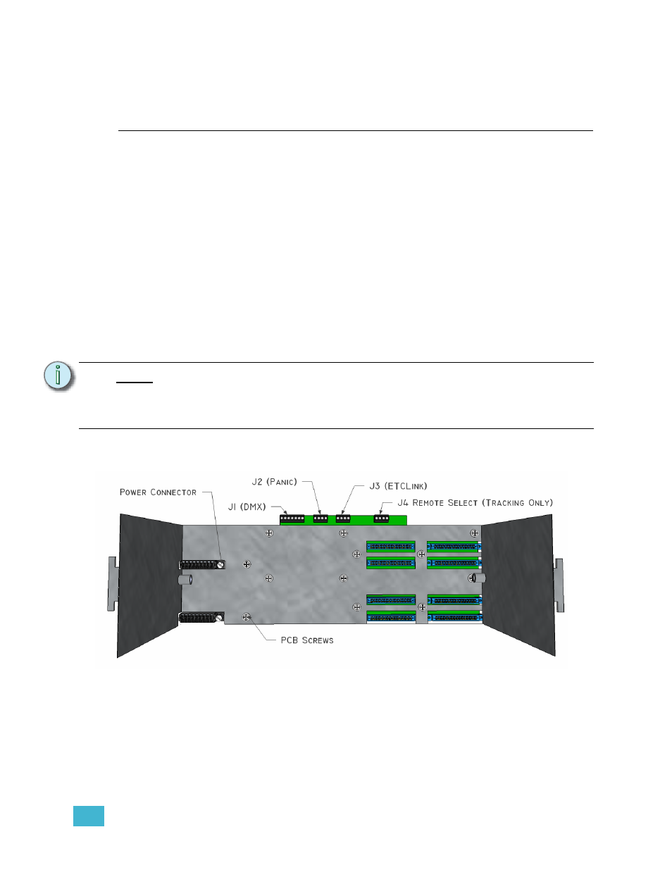
Unscrew the power backplane connector(s) from the old backplane metal
Step 2:
Feed the power connectors through the backplane metal so they are loose next
to the phase bars.
Step 3:
Unscrew the backplane PCB from the backplane metal by undoing the remainder
of the screws
Step 4:
Unscrew the backplane metal from the rack by undoing the two screws that go
N o t e :
Many of the components you will be removing are valuable dimming components
and can be used by ETC to support other systems.
Please return old ECEM processors, ECEM backplanes, and fan relays to the
local ETC office (see
for address).