Install the new backplane, Terminating the ethernet cable inside the rack – ETC Sensor CE Rack (ESR) ECEM to CEM3 Retrofit User Manual
Page 12
10
CEM3 Sensor ESR Rack Retrofit Manual
Terminating the ethernet cable inside the rack
Since you will be adding ethernet capability to your ESR rack, ETC has provided the CAT5
Termination Kit (ETC Part#4101A2003). This kit includes a CAT5 connector and a small
surface mount box (called a “Biscuit Box”) as well as an instruction sheet.
Follow the instructions in this kit for terminating the ethernet cable at the CAT5 connector
and enclosing the connector in the biscuit box. The biscuit box will then be mounted inside
of the ESR rack in the next section.
Install the New Backplane
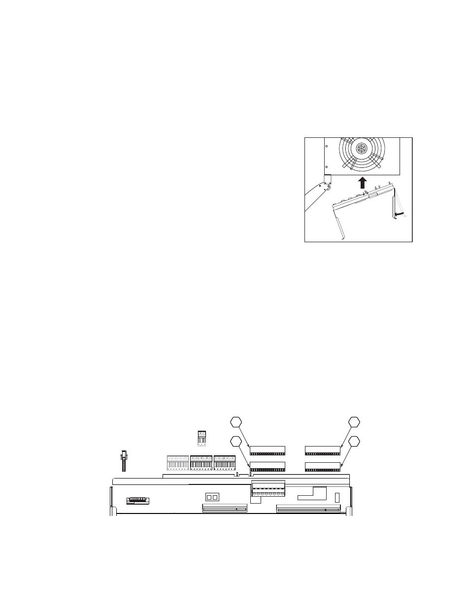
Step 1:
Bend one arm of the new backplane metal in
towards the opposite arm (about 30 deg).
Step 2:
Insert the backplane metal on an angle. Then
straighten it once it is past the face of the rack.
Push it into the rack far enough that it stays in
place, but leave yourself some room to make
the power and data connections.
Step 3:
Make the power and data connections on the
backplane.
a: Install the dimmer output ribbon cables.
Open the black retaining tabs for each
connector until they are at a 45° angle to the
backplane. Press the ribbon cables into their respective locations until the tabs
lock in place at a 90° angle to the backplane.
Note: The order/layout for the cables is not the same as on the old backplane
(see illustration below). Make sure the proper side is facing up on each
connector and that each connector is fully seated.
b: Install the power harness (Look at the pin shapes for proper orientation. It will
only fit one way.)
c: Install the DMX connections. (The wires travel out of the top on both styles of
connectors.)
d: Install the 3-pin beacon connector (The wires travel out of the top of the
connector)
e: Connect the CAT5 biscuit box to the ethernet connector on the backplane using
the 1' CAT5 Ethernet cable. (Not shown in the drawing below for clarity.)
•
In an ESR12 or ESR24, use the double-stick tape (on the box) to secure the
biscuit box to the bottom of the rack behind the backplane.
•
In an ESR36 or ESR48, use the double-stick tape (on the box) to secure the
biscuit box to the interior rear wall of the rack, behind the backplane.
Step 4:
Push the backplane completely into place in the rack. Be careful not to disrupt
the power and data connections you just made. Make sure none of the wiring
DMX A
DMX B
DMX Thru
Beacon
Power
CEM3 Ribbon Cable Layout
1
2
3
4
(25-48)
(73-96)
(49-72)
(1-24)