Enerpac WCR-Series User Manual
Page 6
6
ENGLISH
Fig. A
3
Assembly and adjustments
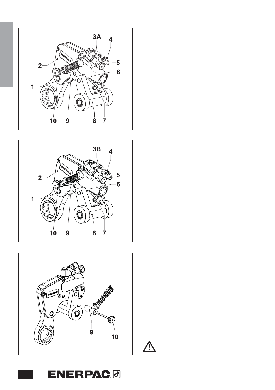
3.1 Overview and features (fig. A or B)
1 Spanner
2 Roller
Cassette
3A Swivel
manifold
(standard)
3B TSP-Pro
Swivel
manifold
(optional)
4
Advance hose connection
5
Return hose connection
6
Hydraulic drive unit
7
Cassette release lever
8
Reaction roller bracket and rollers
9 Positioning
handle
10 Thumb
screw
3.2.1 To attach the positioning handle
(fig. C)
•
Secure the positioning handle (9) with
thumb screw (10). Tighten hand tight.
Note: handle can be installed on
either side of wrench (as needed).
3.2.2 To remove the cassette (fig. D)
•
Make sure the piston is fully retracted.
•
Hold the tool with the drive unit
pointing upwards.
• Swing
the
reaction roller bracket
(8)
inward, toward center of tool.
•
Pull the release lever (7) outwards.
•
Remove the cassette (2) from the
hydraulic drive unit (6).
3.2.3 To attach the cassette (fig. D and E)
•
Make sure the retract link (11) aligns
with the slot (12) in the spanner (1).
Rotate the piston rod if necessary.
•
Pull the release lever (7) outwards.
•
Push the spigot (13) through the hole
in the cylinder locating plate (14).
•
Push the release lever (7) back into
the cassette (2). Make sure the ball
detent clicks into place.
Do not operate the tool if the cassette
release lever is not fully closed.
Fig. C
Fig. B