Main and auxiliary feedback combinations – ElmoMC ExtrIQ Digital Servo Drives-Solo Hornet User Manual
Page 32
Solo Hornet Installation Guide
Installation
MAN-SOLHRNIG (Ver. 1.003)
32
4.7.2.
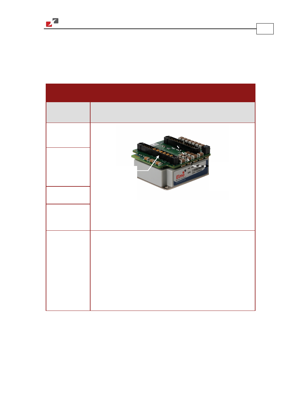
Main and Auxiliary Feedback Combinations
The Main Feedback is always used in motion control devices whereas Auxiliary Feedback is
often, but not always used. The Auxiliary Feedback connector on the Solo Hornet has three bi-
directional pins (CHA, CHB and INDEX). When used in combination with Main Feedback, the
Auxiliary Feedback can be set, by software, as follows:
Main
Feedback
Auxiliary Feedback: Output
Software
Setting
YA[4] = 4
(Auxiliary Feedback: output)
Incremental
Encoder Input
Interpolated
Analog
(Sine/Cosine)
Encoder Input
Resolver Input
Potentiometer/
Tachometer
Input
Typical
Applications
Analog Encoder applications where position data is required, in the
Encoder’s quadrature format, for other purposes such as position
controllers and/or other drives.
Resolver applications where position data is required in the Encoder’s
quadrature format, for other purposes such as position controllers
and/or other drives.
Potentiometer and Tachometer applications where position data is
required, in the Encoder’s quadrature format, for other purposes such
as position controllers and/or other drives.
Main Feedback:
Incremental Encoder
Interpolated Analog
(Sin/Cos) Encoder
OR Resolver
OR Potentiometer
OR Tachometer
Auxiliary Feedback:
Emulated Differential
Buffered Encoder
Output