J3 general i/o port – ElmoMC SimplIQ Analog Servo Amplifiers-Cymbal User Manual
Page 27
Cymbal Installation Guide
Installation
MAN-CYMIG (Ver. 1.3)
27
3.5.3.1.
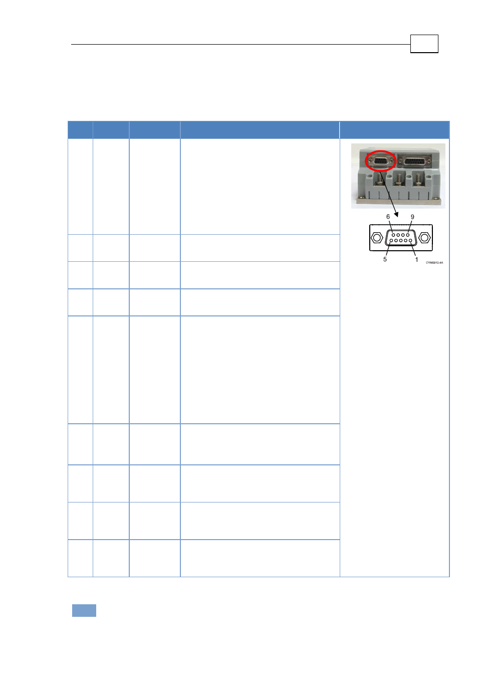
J3 General I/O Port
Port J3 has a 9‐pin D‐Sub female connector. When assembling this I/O cable, follow the
instructions in Section 3.5.2 Control, I/Os and Halls Cable Assemblies using a 9‐pin a metal case
D‐Sub male connector (plug).
Pin Signal Function
Description
Pin Position
1
AOK
Amplifier
OK
When the amplifier under normal
operating conditions, this output is in
the “active low“ state. When a failure
occurs, this output is changed to the
“open” state.
The optocoupler is an isolated, open
collector NPN type.
Maximum voltage = 30 V
Maximum current = 8 mA
“On” voltage: V
OUT(On)
< 0.8 V
9‐Pin Female
2
SO1
Status
output 1
Status indication output 1. Specification
same as in pin J3/1.
3
SO2
Status
output 2
Status indication output 2. Specification
same as in pin J3/1.
4
SO3
Status
output 3
Status indication output 3. Specification
same as in pin J3/1.
5
EN+
Enable +
“Amplifier Enable” function. To enable
operation of the amplifier, the
optocoupler must be energized by
applying voltage between this pin (+) and
pin J3/6 (‐).
The optocoupler is isolated from the
amplifier.
“OFF” voltage: 0 V < Vin < 1 V.
“ON” voltage: 2.5 V < Vin < 10 V, 5 V
typically with current consumption
2.5 mA.
6
EN‐
Enable ‐
Negative voltage input of “Amplifier
Enable” function.
Optocoupler is isolated from the
amplifier. For details, see pin J3/5.
7
SORET
Status
output
return
Status output common AOK, SO1, SO2,
SO3.
Isolated from circuit common.
8
SORET
Status
output
return
Status output common AOK, SO1, SO2,
SO3.
Isolated from circuit common.
9
SORET
Status
output
return
Status output common AOK, SO1, SO2,
SO3.
Isolated from circuit common.
Table 8: J3 I/O Cable ‐ Pin Assignments
Note:
Amplifier enable (EN+, EN‐) can be enabled from J2 or J3.
J3
Female
www.elmomc.com