Elkhart Brass Sidewinder 7161 EXM UHP User Manual
Page 8
EXM UHP– Installation Instructions
(Step 1 – Mount and Wire All System Components)
8
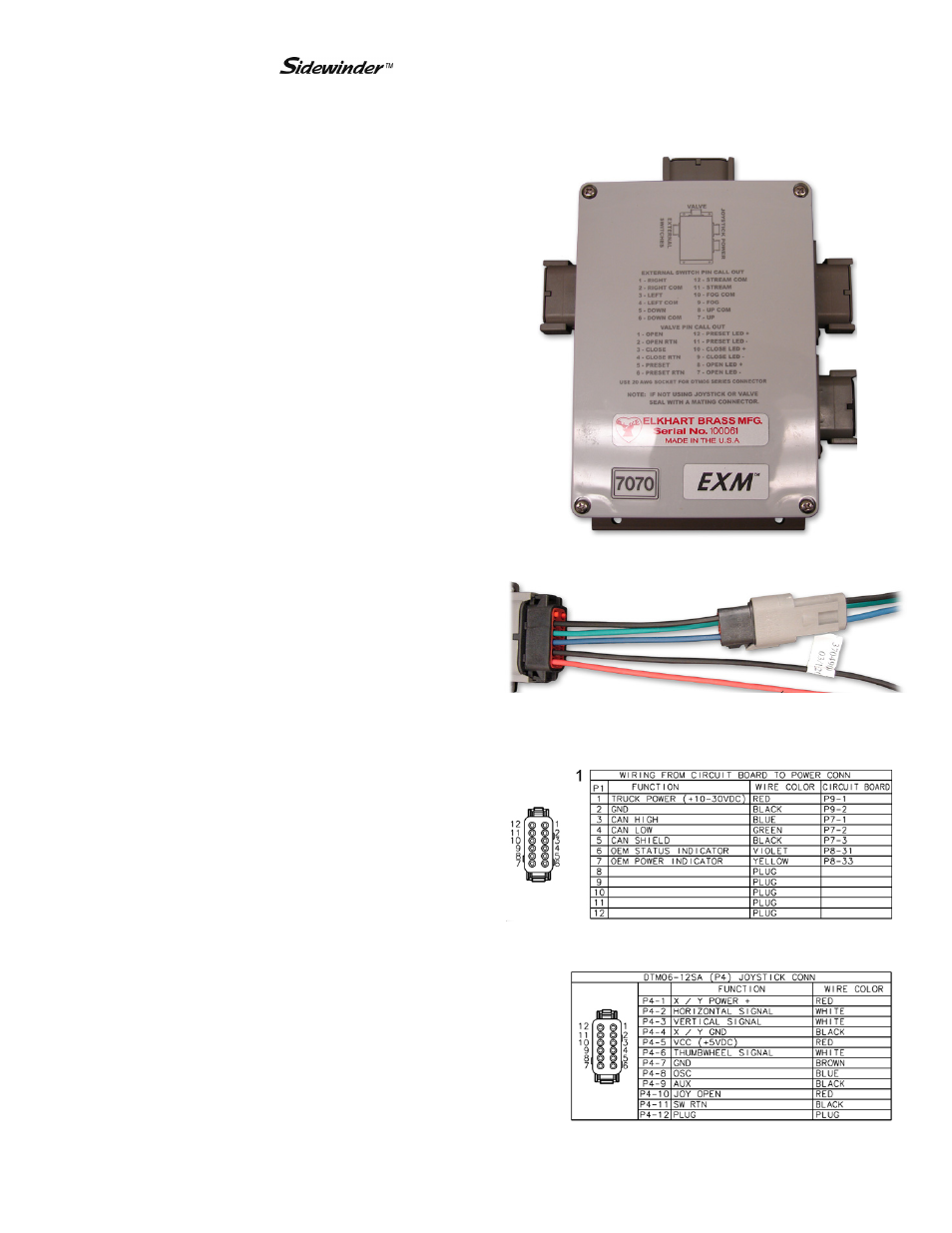
B. Joystick Controller and OEM Interface Module –
Using the template shown on page 28, drill
all holes shown onto the surface intended for
mounting the Joystick Controller.
Mount the Joystick Controller using the
supplied 10-24 x ½” screws using blue
Loctite 242 or equivalent.
Using the template shown on page 27, drill
all 4 of the 7/32” holes shown.
Mount the OEM Interface Module with four
10-24 x ½” screws using blue Loctite 242 or
equivalent.
Connect the plug coming from the Joystick
Controller stick to plug 2 on the OEM
Interface Module. (See picture to the right)
If the Joystick/OEM will use CAN
communication, connect the green, black,
and blue leads coming from plug 1 to the
appropriate CAN line. (See picture below)
Supply power to the OEM Interface Module
and Joystick by connecting the red and black
leads coming from plug 1 to an appropriate
power source. (See picture on previous
page)
Install a 1 Amp fuse into the positive power
lead of the OEM Interface Module for a 12V
system (1/2 Amp for 24V system).
Refer to the respective plug figures on the
previous page for information on the plugs’
pins.
For information regarding external switches
and customer supplied joysticks, refer to the
pin information found on the Module cover.
If there are any unused OEM Interface
Module connections, plug the connections
with appropriate Deustch connectors and
plugs.
Joystick Plug Information
2
OEM Interface Module Plug Information
1
2
1
Valve Plug