Det-Tronics U7652B, C Unitized UV/IR Flame Detector User Manual
Page 16
14
• For the IR module, thread the wire leads and
keyed connector plug through the slotted open-
ing on the side of the IR module. Plug the IR
module intor the two banana plugs inside the
junction box cover (Figure 17). Connect the
keyed plug to the 4-pin connector on the IR
module. Tuck the leadwires inside the module
to prevent binding or wire damage.
6.
Ensure that the O-rings at the base of the sensor
housing are positioned correctly and are in good
condition. (Refer to the “Maintenance” section for
complete information regarding care of O-rings.)
7.
Re-install the sensor housing. Hand tighten the
sensor housing into the base until the O-ring is
fully seated.
8.
Re-install the cover locking device (if used).
9.
Inspect the viewing windows and
oi
rings and
clean if necessary. Also check the position of the
oi
rings (refer to Figure 2).
10. Perform the “Startup and Checkout Procedure
(Manual
oi
Test)” as described in this manual
before returning the system to normal operation.
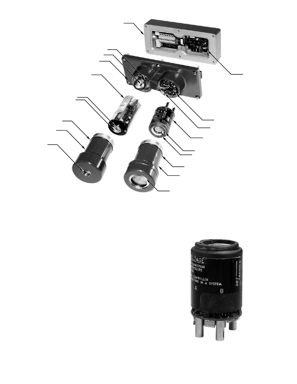
B1330
JUNCTION BOX
MOUNTING PINS
oi TEST LAMP (2)
O-RING
IR SENSOR HOUSING
IR oi RING
UV SENSOR MODULE
O-RING
oi TEST LAMP
UV SENSOR HOUSING
UV oi RING
IR SENSOR MODULE
UV TERMINAL BLOCK
MOTHERBOARD
ASSEMBLY
LED (2)
BANANA PLUG
LED (2)
JUNCTION BOX COVER
IR CONNECTOR PLUG
Figure 15—U7652 Detector Parts Identification
Figure 16—Self Aligning UV Sensor Module