Det-Tronics U7652B, C Unitized UV/IR Flame Detector User Manual
Page 15
13
95-8385
2.
To verify proper IR sensor operation, expose each
operating UV/IR detector to the ultraviolet energy
from the model W8066 UV test lamp. The model
W867 UV/IR test lamp also may be used by first
completely covering the IR sensor portion of the
detector with solid material, and then exposing
only the UV portion of the detector to the output of
the W867 test lamp. Ensure that the test lamp is
within one (1) meter of the detector, and aimed
directly at the center of the detector lens. Proof of
a successful test is no fire alarm output from the
detector. Any UV/IR detector that does respond
to only UV radiation may have a faulty IR module
and will require further inspection. Note that
some Det-Tronics UV/IR detectors will provide a
UV-only alarm that must not be confused with the
fire alarm output.
3.
To verify proper UV sensor operation, completely
cover only the UV sensor and then expose the IR
sensor to the output from the W867 UV/IR test
lamp. Proof of a successful UV test is no fire
alarm output from the detector. Ensure that the
W867 UV/IR test lamp is within one (1) meter of
the detector. Do not use the model W8066 UV
test lamp for this test.
4.
Finally, expose each operating, uncovered UV/IR
detector to the output of the model W867 UV/IR
test lamp to re-confirm fire detection capability.
Ensure that the W867 UV/IR test lamp is within
one (1) meter of the detector, and verify that the
detector does provide a fire alarm output.
If a damaged detector sub-assembly in the field has
been identified, exchange it with a different sub-
assembly from a known good detector, then re-
assemble and re-test until proper operation is
observed. If abnormal operation is evident, start with
the sensor exchange first, then the detector cover
assembly, and finally the detector mother board
assembly. Always remove system power before ser-
vicing any detector, and always ensure that proper
electrostatic grounding procedures are followed
before handling.
Return any damaged sub-assemblies or detectors to
the Det-Tronics Service Center for inspection and
repair. Please call for a return material identification
number before returning equipment to the factory.
SENSOR MODULE REPLACEMENT PROCEDURE
To replace a defective module:
CAUTION
Do not open the detector housing in a hazardous
location without first removing power, including
power to the relay contacts.
1.
Remove power from the detector and relay con-
tacts.
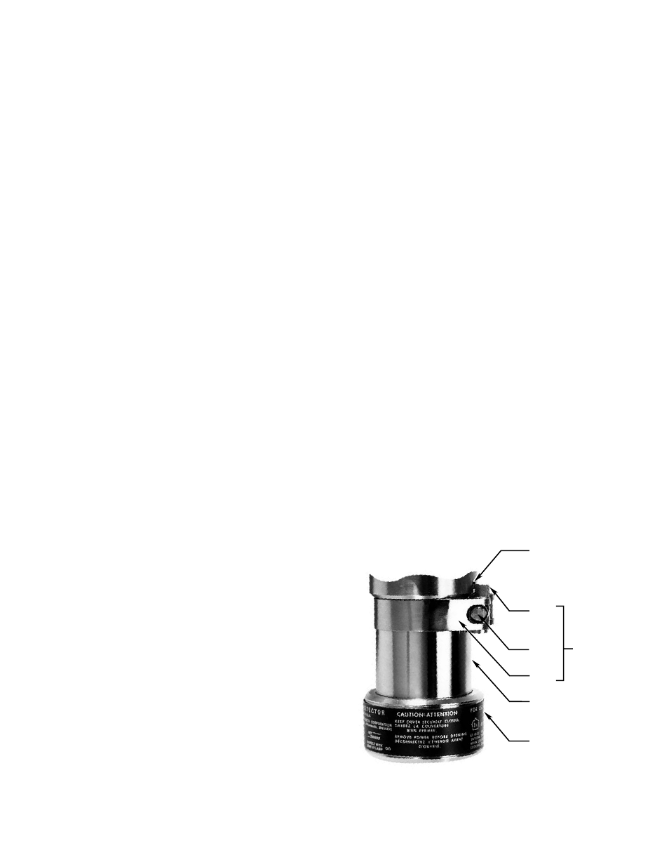
2.
If the detector is equipped with cover locking
devices (see Figure 14 ), loosen the clamp and
disengage the “catch” from the blind hole for the
appropriate sensor.
3.
Remove the sensor housing (see Figure 15).
4.
Remove the defective sensor module.
5.
Determine the proper orientation for the new sen-
sor module (with the
oi
test lamps positioned at
the top or side of the detector), then install the
module.
• For the UV module (Figure 16), line up the
longest banana plug on the terminal block with
the hole in the printed circuit board of the mod-
ule. See Figure 15. Firmly press the module
into place on the terminal block, taking care
not to touch the glass envelope of the sensor
module. If the UV sensor module is supplied
with a jumper plug “J,” remove the jumper plug
from the detector tube module and discard it.
Jumper plug “J” is supplied for installations in
which the tube module is used with other detec-
tor models.
BLIND HOLE
COVER
LOCKING
ASSEMBLY
CATCH
CLAMP
SCREW
STRAP
BARREL
LENS CAP
A1078
Figure 14—Cover Locking Assembly (Optional)