Is used, wire the manual, Test – Det-Tronics U7652B, C Unitized UV/IR Flame Detector User Manual
Page 11
Note that non-isolated operation requires installation
of a jumper wire between pins CON 1-1 and CON 1-9
(current sourcing) or between pins CON 2-2 and CON
2-9 (current sinking) on the detector terminal block.
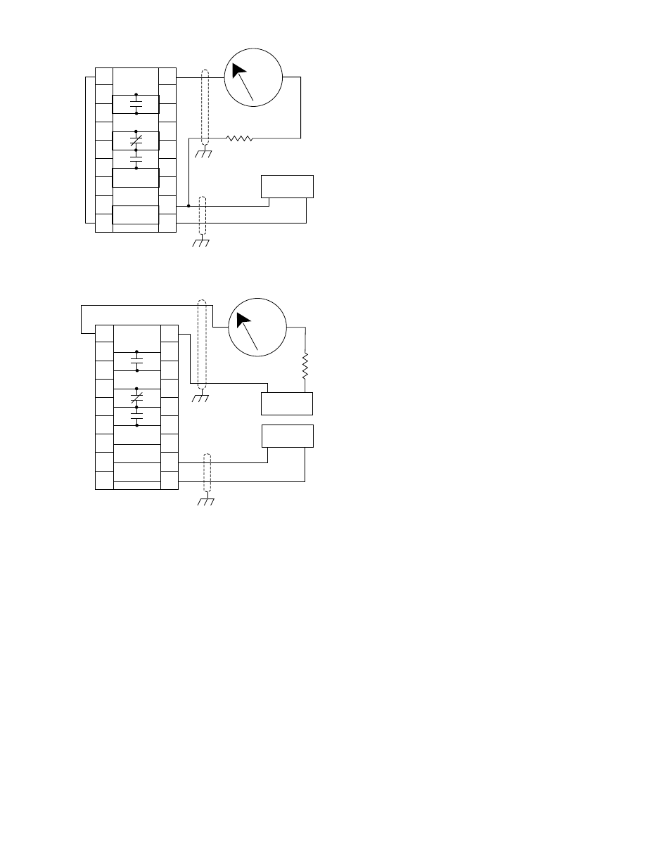
Figure 13 — U7652C Detector with 4 to 20 ma
Output Wired for Isolated Current
Sinking Output
Note that isolated operation requires the use of a sep-
arate power supply.
1.
Mount the detector and mounting bracket assem-
bly. The mounting surface should be free of
excessive heat and vibration.
2.
Remove the junction box cover.
3.
Route the field wiring through the detector conduit
entry.
4.
Connect the leadwires to the appropriate screw
terminals on the terminal blocks inside the junc-
tion box. Connect the shield to earth ground at
the power source. Do not ground the shield at
the detector/controller housing (unless required
by local codes).
5.
If manual
oi
is used, wire the manual
oi
test
switches (optional) by connecting a normally
open switch, capable of switching 1 ma at 5 vdc
and with contact resistance no more than 25
ohms, between the negative (–) side of the dc
power source and the terminal marked “
oi
” on
the detector terminal block. Each detector should
have its own
oi
test switch to allow individual
detector testing.
6.
Check all field wiring to be sure that the proper
connections have been made, and also double
check the jumper plugs for correct position. If
conduit is used, pour the conduit seals and allow
them to dry.
7.
Re-install the junction box cover, ensuring that the
9-pin “D” connectors are properly mated between
the cover and the circuit board inside the enclo-
sure. The six screws must be tight to ensure a
metal-to-metal fit for explosion-proof and water-
tight integrity of the junction box.
8.
Inspect and clean (if necessary) the detector
viewing windows and
oi
rings by following the
instructions in the “Maintenance” section.
9.
Re-install the
oi
rings. The opening should be
pointed down to minimize the accumulation of
moisture or contaminants behind the ring. Verify
that the
oi
test lamp is at the top or side of each
sensor.
10. If the detector is so equipped, install the air
shields on each sensor housing, then connect the
air supply line to the air shields.
DETECTOR PROGRAMMING
The U7652 provides three standard field pro-
grammable options:
— 0.5 or 3 second response time
— Latching or non-latching alarm output
— Automatic or manually activated
oi
test.
9
95-8385
D1441
+
–
24 VDC
LOAD
875 Ω MAX
AT 24 VDC INPUT
+
–
4 TO 20 MA
MINIMUM OF 6.5 VDC REQUIRED
BETWEEN CON 1–9 AND CON 2–9
9
8
7
6
5
4
3
2
1
9
8
7
6
5
4
3
2
1
CON 1
CON 2
+
–
4 TO 20 MA
FIRE RELAY
FAULT RELAY
Figure 12—U7652C Detector with 4 to 20 ma Output Wired for
Non-Isolated Current Sourcing Output
MINIMUM OF 6.5 VDC REQUIRED
BETWEEN CON 1–9 AND CON 2–9
D1442
875 Ω MAX
AT 24 VDC INPUT
+
–
24 VDC
+
–
24 VDC
+
–
4 TO 20 MA
9
8
7
6
5
4
3
2
1
9
8
7
6
5
4
3
2
1
CON 1
CON 2
+
–
4 TO 20 MA
FIRE RELAY
FAULT RELAY
Figure 13—U7652C Detector with 4 to 20 ma Output Wired for
Isolated Current Sinking Output