Det-Tronics NTMOS IP66/IP67 H2S Gas Detector User Manual
Page 7
2.1
95-8670
5
3. Confirm that the power and signal cabling for the
gas detector is the proper size and type, and is
appropriate for the application requirements. After
all electrical connections are made, double check the
terminations against the wiring diagrams to ensure
that all connections are properly terminated.
4. The NTMOS Detector is designed to operate at 24
Vdc nominally. Measure the delivered voltage at the
detector, especially for long cable runs, to ensure
that possible voltage drops have not compromised
the necessary 24 Vdc supply voltage. This
should be considered during system design and
commissioning.
NOTE
Do not apply power to the system with the junction
box cover removed unless the area has been
de‑classified.
5. After confirming that the detector is properly installed
and wired, all electrical terminations are properly
made, and proper operating voltage is provided to
the detector, the installer may conduct the startup
procedure.
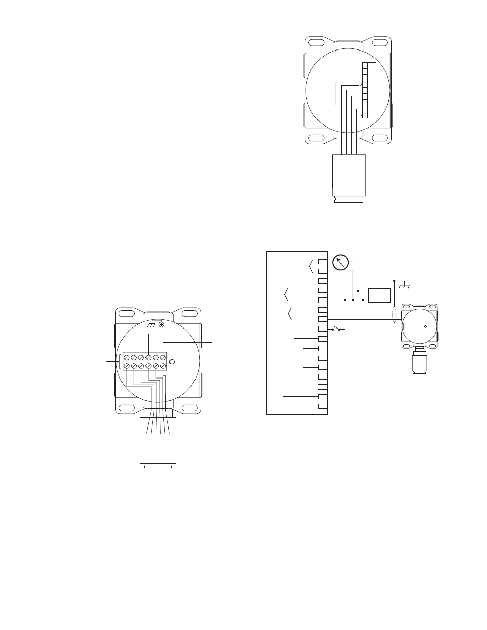
Figure 5—NTMOS Detector Wired to U9500 Infiniti Transmitter
E2361
INFINITI TRANSMITTER
NO
COM
NC
S
–
+
RESET
CA
L
FA
UL
T RELA
Y
PO
WER
PW
IN
GREY
OR
ANGE
BLA
CK
RED
YELL
O
W
WHITE
NTMOS H2S
DETECTOR
Figure 4—NTMOS Detector Wired to GDTB Termination Box for Stand-
Alone Operation
NOTES:
1 CUSTOMER SUPPLIED NORMALLY OPEN
MOMENTARY CLOSURE SWITCH CAN BE
USED TO INITIATE CALIBRATION. MOMENTARY
CONNECTION TO POWER SUPPLY MINUS
(24 VDC -) INITIATES THE CALIBRATION
SEQUENCE.
2 PLACE MAGNET AT THIS
LOCATION APPROXIMATELY ONE
INCH ABOVE MOUNTING
SURFACE TO ACTUATE SWITCH.
C2447
GDTB TERMINATION BOX
NTMOS H2S
DETECTOR
RED
+24
RET
4-20
CA
L
COMM 1
COMM 2
+24
RET
4-20
CA
L
COMM 1
COMM 2
BLA
CK
WHITE
YELL
O
W
GREY
OR
ANGE
24 VDC +
24 VDC –
4-20 MA
CAL SWITCH
1
INTERNAL
MAGNETIC
REED SWITCH
2
Figure 6—NTMOS Detector Wired to Model R8471B Controller through
the GDTB Termination Box
CURRENT OUTPUT
CHASSIS GROUND
POWER
SENSOR
EXTERNAL RESET
HIGH ALARM
HIGH ALARM / OC
AUX. ALARM
AUX. ALARM / OC
LOW ALARM
LOW ALARM / OC
FAULT
FAULT / OC
1
3
4
5
6
7
8
9
10
11
12
13
14
15
16
–
+
+
–
+
–
18 TO 32
VDC
POWER
SIGNAL
RESET
24 VDC
+
–
2
B2535
GDTB
TERMINATION BOX
R8471B CONTROLLER
NTMOS H2S
DETECTOR
4 TO 20 MA
24 VDC –
24 VDC +
+
–
4-20 MA
NOTES:
1. TAPE OFF ALL UNUSED NTMOS DETECTOR
LEADS TO PREVENT SHORTING.
2. REFER TO FIGURE 4 FOR ADDITIONAL
WIRING INFORMATION WHEN USING
THE GDTB WITH THE NTMOS DETECTOR.