Figure 2—ntmos detector wired to flexvu model ud10 – Det-Tronics NTMOS IP66/IP67 H2S Gas Detector User Manual
Page 6
95-8670
2.1
4
INSTALLATION AND WIRING
1. Determine the best mounting locations for the
detector. Mount the detector with the sensing
element pointing down (18 inches from surfaces
below). The junction box (GDTB or transmitter
housing) is intended for flat-surface mounting, such
as on a wall or post. A spacer or stand-off (1/4 to 1/2
inch) may be needed to allow adequate clearance
for the detector and calibration cup. The junction box
should be electrically connected to earth ground.
NOTE
To ease installation and future removal, use Teflon
tape for the male threads of the detector. The
Lubriplate grease (see Ordering Information for
part number) is used to lubricate the threads on the
junction box cover. The use of silicone grease must
be avoided.
2. Terminate all detector wiring at the proper terminals
and verify that bonding between detector housing-
to-ground terminal is less than 0.1 ohm. Refer to
Table 1 and Figures 2 to 6 for wiring details:
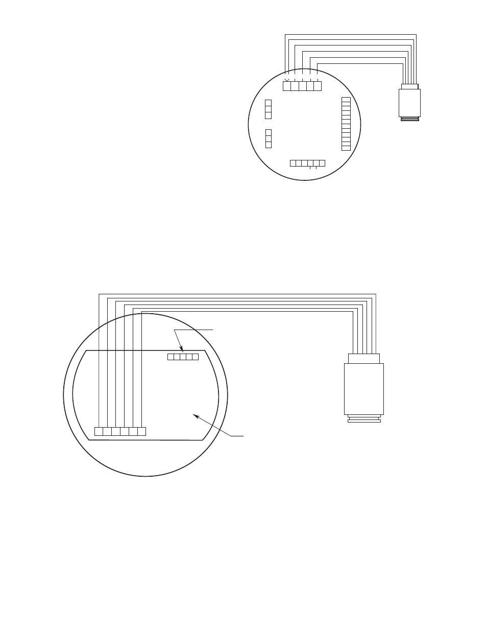
Figure 2—NTMOS Detector Wired to FlexVu Model UD10
NTMOS H2S
DETECTOR
BLACK
RED
GREY
1
YELLOW
WHITE
ORANGE
1
UD10
DISPLAY UNIT
C2448
Sensor Connector
Power Supply Connector
Output Loop
Connector
MODBUS
Connector
R
ela
y Connect
or
P1
J2
J3
J4
P2
4-20 mA +
4-20 mA –
SHIELD
COM
RS485 A
RS.485 B
HIGH ALARM COM
HIGH ALARM NC
HIGH ALARM NO
AUX ALARM COM
AUX ALARM NC
AUX ALARM NO
LOW ALARM COM
LOW ALARM NC
LOW ALARM NO
FAULT COM
FAULT NC
FAULT NO
24 VDC
–
24 VDC
+
SHIELD
24 VDC
–
24 VDC
+
SHIELD
SHIELD
C
ALIBR
A
TE
24 VDC
–
4-20 mA
24 VDC
+
P1-3
P1-2
P1-1
J2-3
J2-2
J2-1
J4-1
J4-2
J4-3
J4-4
J4-5
J4-6
J4-7
J4-8
J4-9
J4-10
J4-11
J4-12
J3-1
J3-2
J3-3
J3-4
J3-5
P2-6
P2-5
P2-4
P2-3
P2-2
P2-1
1
GREY AND ORANGE WIRES ARE FOR
FACTORY USE ONLY. THEY CAN BE
TAPED OFF IF LOCAL CODES ALLOW,
OR CONNECTED TO THE POWER
SUPPLY MINUS (24 VDC –) OR SHIELD
TERMINALS.
NOTE
UD10 HOUSING MUST BE ELECTRICALLY
CONNECTED TO EARCH GROUND
Figure 3—NTMOS Wired Directly to UD10 via the NTMOS Connector Board
NOTE 1
REMOVE UD10 ELECTRONIC MODULE FOR ACCESS
TO NTMOS CONNECTOR BOARD (NO TOOLS REQUIRED).
NOTE 2
GREY AND ORANGE WIRES FOR FACTORY USE ONLY.
NOTE 3
HOUSINGS MUST BE ELECTRICALLY CONNECTED TO
EARTH GROUND.
UD10
DISPLAY UNIT
B2493
J2
P1
COM 1 (GR
A
Y)
COM 2 (OR
ANGE)
C
AL (YELL
O
W)
R
TN (BLA
CK)
4/20 (WHITE)
24V (RED)
SHIELD
CA
L
RT
N
4/20
24V
CONNECT TO UD10 MODULE’S J3 WITH
FACTORY INSTALLED CABLE
NTMOS CONNECTOR BOARD
NTMOS
H2S DETECTOR
RED
BLA
CK
WHITE
YELL
O
W
GREY
OR
ANGE