Det-Tronics NTMOS IP66/IP67 H2S Gas Detector User Manual
Page 5
2.1
95-8670
3
DETECTOR POSITIONING
Proper detector location is essential for providing
maximum protection. The most effective number
and placement of detectors varies depending on the
conditions at the job site. The individual designing
the installation must rely on experience and common
sense to determine the number of detectors needed
and the best locations to adequately protect the area.
The following factors are important and should be
considered for every installation:
1. Since hydrogen sulfide is a highly toxic gas, a
primary consideration in determining optimum
detector locations is to identify where the most
likely release point of the hazard is located. Use
local or recommended practices to identify these
locations.
2. Factors such as vapor density should also be
considered when determining detector locations.
Hydrogen sulfide is slightly heavier than clean air,
and therefore may tend to settle near the floor or
ground, unless it is heated, mixed with other gases
that are lighter than air, or prevented from doing so
by ambient air movement patterns.
3. How rapidly will the H
2
S gas diffuse into the air?
Select a location for the detector as close as practical
to an anticipated leak source. As gas disperses it
becomes difficult to detect as it is diluted.
4. Detectors should be placed where the most
concentrated accumulation of hydrogen sulfide gas
is anticipated. Also consider the fact that some
ventilation systems do not operate continuously,
and therefore areas with poor circulation should be
evaluated for toxic gas accumulation.
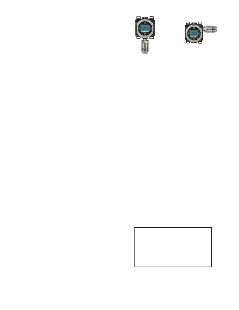
5. The detector must always be installed pointing
straight down (see Figure 1).
6. The detector must be accessible for testing and
calibration. Allow adequate space for attaching
the NTMOS approved H
2
S calibration device.
See Specifications section of this manual for
dimensions.
7. Exposure to excessive heat or vibration can cause
premature failure of electronic devices, and should
be avoided if possible. Shielding the device from
intense sunlight will reduce solar heating. For details
regarding the operating and storage temperatures of
the NTMOS Detector, refer to “Temperature Range”
in the Specifications section.
WIRING REQUIREMENTS
The maximum allowable distance between the NTMOS
Detector and transmitter/control device is limited by the
resistance of the cabling used. To ensure proper operation,
a minimum of 18 Vdc is required at the detector.
When mounted remotely from the transmitter/controller,
shielded cable or dedicated conduit is required for wiring
the detector. Ground the shield at the transmitter/controller
end only.
In applications where the detector cable is installed
in conduit, the conduit should not be used for wiring to
other electrical equipment whenever possible. If other
equipment power wiring is run in the same conduit, the
detector cabling must be shielded.
If an additional signal conditioning or relay output
transmitter is being used along with the NTMOS Detector,
refer to the specific transmitter manual for detailed wiring
instructions.
It is important that moisture not be allowed to come in
contact with the electrical connections of the system.
Use proper piping techniques, breathers, glands, and
seals as required to prevent water ingress and/or maintain
explosion-proof ratings.
* If the yellow wire is not being used, do not connect it to dc minus .
** For factory use only . Connect to isolated Spare terminal or
tape off to prevent contact to any conductor .
Wire Color
Function
Red
24 Vdc +
Black
24 Vdc –
White
4-20 mA Signal
Yellow*
Calibrate Line
Orange**
Connect to Isolated Spare
Grey**
Connect to Isolated Spare
Table 1—NTMOS Detector Wiring Identification
Figure 1—Recommended Orientation of NTMOS Detector (with UD10)
CORRECT
INCORRECT