Control Company 4380 RADIO-SIGNAL REMOTE HUMIDITY METER/THERMOMETER User Manual
Page 2
Control Company Cat. No. 4380
Traceable
®
is a registered trademark of
Control Company.
©
2013
Control Company
. 92-4380-00 Rev. 0 1
11313
TRACEABLE
RADIO-SIGNAL
REMOTE HUMIDITY
METER/
THERMOMETER
INSTRUCTIONS
®
Press and hold the button for rapid-scrolling sequence
by increments of 5.
3. Repeat the steps to set the upper humidity setting and
the lower temperature and humidity settings.
4. When finished, press HI/LO to set another limit or
wait 16-seconds and the unit will automatically return
to the normal display. The respective HI, LO or both
indicators will light up to signify the status of the alarm.
If another channel other than channel one is selected,
when the alarm activates the display will switch to
channel-1 and the display will flash. If left untouched,
the alarm will activate for 1-minute. Press any key to
momentarily stop the alarm. The alarm will activate again
if the limit continues to exceed the set limits.
Note: If a second limit is passed while an alarm is active,
the first alarm will complete its 1-minute cycle and the
alarm will continue to activate for a second minute to
indicate that a second limit has been surpassed.
To disable alarm:
1. Enter the setting mode by pressing HI/LO.
2. Then press AL ON/OFF.
The alarm has been disabled and will not sound at the
previously set limit.
To disable a sounding alarm:
Press any button, the alarm sound will stop.
DISCONNECTED SIGNALS
If without obvious reasons the display for a particular
channel goes blank, press IN/REMOTE to force an
immediate search.
If that fails, check:
1. Remote unit for that channel to see if it is still in place.
2. Batteries of both the remote unit and the main unit.
Note: When the temperature falls below the freezing
point, the batteries of outdoor remotes will freeze,
lowering their voltage supply and effective range.
3. Transmission is within range and path is clear of
obstacles and interference. Shorten distance if
necessary.
TRANSMISSION COLLISION
Signals from other radio devices may interfere with
those of this product and cause temporary reception
failure. This is normal and does not affect the general
performance of the product. The transmission and
reception of temperature readings will resume once the
interference recedes.
LOW BATTERY WARNING
When it is time to replace batteries, the respective
low-battery indicator will show up when the respective
channel is selected. The battery indicator for the main
unit will be shown on the indoor temperature display.
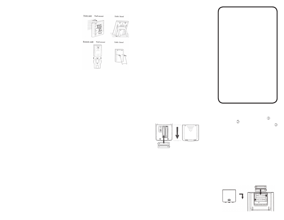
HOW TO USE THE BENCH STAND OR WALL
MOUNTING
The main unit has a retractable bench stand, which when
flipped open, can support the unit on a flat surface. Or,
close the stand and mount the unit on a wall using the
recessed screw hole.
The remote unit comes with a wall-mount holder and a
removable stand. Use either to hold the unit in place.
THE RESET BUTTON
This button is only used then the unit is operating in an
unfavorable way or malfunctioning. Use a blunt stylus
or straightened paper clip to hold down the button. All
settings will return to default values.
OPERATIONAL DIFFICULTIES
If this temperature meter does not function properly
for any reason, please replace the batteries with new,
high-quality batteries (see “Battery Installation” sections).
Low battery power can occasionally cause any number of
“apparent” operational difficulties. Replacing the batteries
with new fresh batteries will solve most difficulties.
What to do if the unit appears to not be receiving a
signal.—Suggestions
Keep in mind that the remote transmitter sends a signal
to the main receiver every thirty seconds. Be patient, wait
2 minutes to see if a signal has been received.
Make certain that the channel number on the remote
transmitter (displayed on the remote transmitter LCD)
and the channel number on the main receiver (displayed
on the receiver LCD) are identical.
If there are two or more remote transmitters, make
certain that none are set to the same channel number.
Remove the battery cover on the main receiver (unit with
large LCD display). Remove the batteries. Do not put
the batteries in until the remote transmitter is activated.
The goal is to activate the remote transmitter before the
main receiver.
Remove the back panel of the remote transmitter.
Remove the batteries, wait 20 seconds, and put them
back in the unit. Then, using a stylus or straightened
paper clip, press the RESET button. Observe on the
remote transmitter LCD a momentary reset to “888” on
the display, release the RESET button.
Place the batteries in the main receiver unit. Replace the
battery cover. Using a stylus or straightened paper clip,
press the RESET button on the main receiver. Observe
on the receiver LCD a momentary reset to “888” on the
display, release the RESET button.
First make certain that the unit will pick up a nearby
signal. Do this by placing the remote transmitter in a
vertical position. Place the main receiver (large digital
display) in a vertical position approximately 6 feet
away from the remote transmitter. There should be no
obstructions between the units.
Make certain the main receiver is set to the correct
channel. On the main receiver simultaneously press the
IN/REMOTE button. This will force the main receiver
to search for the signal. Again, make certain the main
receiver is still set on the correct channel.
If the main receiver is now displaying the temperature
from the remote transmitter then the units are functioning
correctly. These units will perform within their limitations.
All radio signals are inherently affected by interference or
blockage. Even the most powerful megawatt radio station
transmitter is occasionally blocked when driving. Powerful
cellular phones (which are simply radio transmitters/
receivers) still “drop” calls when interference or blockage
occurs. Some of the causes of interference and blockage
are metal, reflective surfaces, motors, elevators,
florescent lights with electrically noisy ballasts, sparking
environments such as welding, emergency vehicle
radios, power lines, portable/mobile radio transmitters
and walkie-talkies.
BATTERY AND CHANNEL INSTALLATION:
REMOTE UNIT
Remote sensor unit uses two (AAA) size alkaline
batteries. Replace the butteries, when low-battery
indicator of the particular channel lights up on main unit.
Note: Once a channel is assigned to a remote unit, to
change the assigned channel, remove the batteries or
press the reset button.
Follow these steps to install / replace batteries:
1. Slide open the battery compartment door.
2. Insert battery according to polarities shown above.
3. Replace battery compartment door.
Note: Removing/replacing the batteries will
reset the unit to default settings. Revisit Setup
Procedure.
BATTERY INSTALLATION: MAIN UNIT
The main unit uses two AA batteries. To install them:
1. Slide open the battery compartment door.
2. Insert the batteries strictly according to the polarities
shown.
3. Replace the battery compartment door.
4. Replace the batteries when the low-battery indicator of
the indoor temperature lights up.
Note: Removing/replacing the batteries will reset the
unit to default settings. Revisit Setup Procedure.
WARRANTY
, SERVICE, OR RECALIBRA
TION
For warranty, service, or recalibration, contact:
CONTROL COMPANY
4455 Rex Road
Friendswood, Texas 77546 USA
Ph. 281 482-1714 • Fax 281 482-9448
E-mail [email protected] • www.control3.com
Control Company
is
ISO 9001
Quality-Certified
by
DNV
and
ISO 17025 accredited as a Calibration Laboratory by A2LA.