Prepare site • prepare burner • mount burner, Model ezgas pro gas burner — instruction manual, Figure 5 flame rod/ ignitor electrode assembly – Carlin EZGasPro User Manual
Page 8: Figure 4 flame rod and ignitor placement, Bsize, Figure a figure b, Carlin combustion technology, inc
Model EZGas Pro gas burner — Instruction manual
Carlin part number MNEZGas Rev. 10/28/13
– 8 –
Where appliance instructions differ from this manual, follow the appliance instructions.
1. Prepare site • prepare burner • mount burner
(continued)
Inspect/redrill gas orifice when required
• Turn off power to the burner/appliance before proceeding.
• Close main manual gas valve in gas line to burner. Then disconnect
the ground joint union to allow rotating burner combination gas valve.
You must disconnect power to burner and close main
manual gas valve before proceeding. Failure to do so
could result in severe personal injury, death or substantial
property damage.
• Unplug wire harness from combination gas valve.
• Remove the combination gas valve (item 20, page 3) and the orifice
nipple (item 6, page 3). Remove the orifice nipple from the gas valve.
• Read the correct orifice drill size from Table 1, page 7. Then check
actual orifice size using that size twist drill bit.
•
If gas orifice is smaller than required, redrill the orifice to the cor-
rect size, if necessary.
•
If gas orifice is larger than required, obtain a replacement orifice
nipple from Carlin. If necessary, drill the orifice hole in the replace-
ment orifice nipple to the correct size.
Drill the orifice carefully, avoiding drill wobble. Wobble will
cause the orifice to be over-sized. The orifice nipple should
be secured in a vise, if possible, to ensure it is steady dur-
ing the drilling process.
• Write the orifice size on the orifice nipple label (or on the French
label attached to the burner for Canadian installations).
• Replace the gas valve and piping, using only pipe dope listed for use
with liquefied petroleum gases. Make sure the arrow on the orifice
nipple label points in the direction of gas flow.
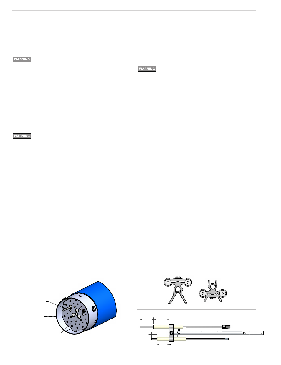
Flame rod and ignitor electrode
• Inspect the burner from air tube end. Flame rod should extend
through the diffuser plate as shown in Figure 4. Ignitor electrode
should be flush with inner face of diffuser plate as shown.
• The flame rod and ignitor electrode must not touch the diffuser or any
grounded metal surface at any point. The flame rod and electrode
should be as close as possible to the centers of the diffuser holes. If
either the flame rod or electrode is closer than 1/16” to the diffuser,
remove assembly (see page 15 for removal instructions and verify
dimensions per Figure 5). Bend the end of the flame rod or ignitor
electrode as required. Replace assembly and check spacing again.
Continue adjusting as necessary until neither rod nor electrode is
closer than 1/16” to the diffuser.
Figure 5 Flame rod/ ignitor electrode assembly
Install gas valve on burner
1. Read WARNING’s on page 9 before installing gas valve.
2. Apply a small amount of pipe dope (suitable for propane gas) to gas
valve outlet connection, gas line nipple and burner gas connection.
Assemble pipe nipple to gas valve. Install gas line nipple in burner
gas connection.
To avoid damage to gas valve, do not hold valve with a
pipe wrench or over-tighten. Use only a crescent wrench
or other means. Failure to comply could result in severe
personal injury, death or substantial property damage.
3. Connect wire harness to valve.
Inspect components and wiring
• Visually inspect all burner components and wiring.
• Verify that wiring is intact and connectors are securely connected.
• Verify that all burner components are in good condition.
Mount burner in appliance
• Verify appliance burner front plate dimensions per page 19.
• Slide gasket supplied with burner over end of air tube.
• Insert burner into appliance opening and bolt in place.
Verify and install diffuser plate
Each plate will be stamped on the face of the diffuser with a letter desig-
nating the diffuser type (Example A, B, C, 9S).
1. Install the diffuser on the air tube by placing the wide tab into the slot
at the end of the air tube with the 90
o
bent tabs of the diffuser plate facing
into the air tube.
2. Fasten diffuser plate to the air tube with the two screws provided.
3. Make sure the flame rod and electrode are not touching the diffuser
plate.
4. If flame rod or electrode is making contact with the diffuser plate the
burner will not prove flame and will enter a lockout condition.
Air tube orientation for right side (motor side) gas supply (Burners
with Adjustable Flange only)
1. The air tube may be rotated from the left side gas inlet to the right side
gas inlet (motor side).
2. Remove the electrode/flame rod assembly as described in the Mainte-
nance section. It should look like Figure A.
3. Remove the four 5/16 screws that hold the air tube to the burner chas-
sis. Now the air tube can be rotated 180
o
so the gas inlet is on the right
side (motor side). Reinstall the four 5/16 screws, securing the tube back
onto the chassis.
4. Remove the screw holding the electrode/flame rod bracket to the alu-
minum rod. Reassemble the electrode/flame rod bracket to the aluminum
rod as shown in Figure B while positioning the flame rod and electrode as
shown in Figure 5.
5. Replace the electrode/flame rod assembly as described in the Main-
tenance section. Note that the aluminum rod must now sit on top of the
nylon washer.
Figure 4 Flame rod and Ignitor placement
QUALITY CHARACTERISTICS
CRITICAL
MAJOR
A
MAJOR
B
MINOR
NO
SYMBOL
CRITICAL
STATISTICAL
SEE QAS 1000 FOR VENDORS QUALITY
ASSURANCE REQUIREMENTS
TOLERANCE UNLESS OTHERWISE SHOWN
FRACTIONAL `1/64 ANGLE `1/2~
DEC. .XX `.01 .XXX `.005
THIS DOCUMENT MAY NOT BE
REPRODUCED WITHOUT WRITTEN
PERMISSION FROM CARLIN
COMBUSTION TECHNOLOGY, INC.
REMOVE BURR AND FLASH FOR
PROPER OPERATION AND GOOD
APPEARANCE
THIRD ANGLE PROJECTION
DO NOT SCALE DRAWING
INTERPRET ALL DIMENSIONS
PER ANSI Y14.5 1994
CARLIN COMBUSTION TECHNOLOGY, INC.
EAST LONGMEADOW, MA U.S.A.
PART
NUMBER
MAT'L
NUMBER
PART
DESC.
MAT'L
DESC.
ITEM
CLASS
ITEM
CLASS
ECN #
REV SH
OF
DRAWING
NUMBER
DRAWN
DATE
SCALE
58572
wmisiaszek
9/4/2013
ECN
BSIZE
ALL LINEAR DIMENSIONS
ARE IN INCHES
REVISION HISTORY
REV
DESCRIPTION
ECN
BY
DATE
.
Released to Production
ECN
MPC
5/4/2009
Ignitor electrode
Electrode bracket
Flame rod
Support rod
1.55"
1 3/4"
0.61"
1 3/8"
Flame rod
Ignitor electrode
Support rod flush at both ends
QUALITY CHARACTERISTICS
CRITICAL
MAJOR
A
MAJOR
B
MINOR
NO
SYMBOL
CRITICAL
STATISTICAL
SEE QAS 1000 FOR VENDORS QUALITY
ASSURANCE REQUIREMENTS
TOLERANCE UNLESS OTHERWISE SHOWN
FRACTIONAL
`
1/64 ANGLE
`
1/2
~
DEC. .XX `
.01 .XXX
`
.005
THIS DOCUMENT MAY NOT BE
REPRODUCED WITHOUT WRITTEN
PERMISSION FROM CARLIN
COMBUSTION TECHNOLOGY, INC.
REMOVE BURR AND FLASH FOR
PROPER OPERATION AND GOOD
APPEARANCE
THIRD ANGLE PROJECTION
DO NOT SCALE DRAWING
INTERPRET ALL DIMENSIONS
PER ANSI Y14.5 1994
CARLIN COMBUSTION TECHNOLOGY, INC.
EAST LONGMEADOW, MA U.S.A.
PART
NUMBER
MAT'L
NUMBER
PART
DESC.
MAT'L
DESC.
ITEM
CLASS
ITEM
CLASS
ECN #
REV SH
OF
DRAWING
NUMBER
DRAWN
DATE
SCALE
wmisiaszek
9/4/2013
ALL LINEAR DIMENSIONS ARE IN INCHES
REVISION HISTORY
REV
DESCRIPTION
ECN
BY
DATE
.
Released to Production
W.M.
04-06-10
Flame rod
End of air tube
Ignitor electrode
*Tip should extend in front of diffuser by 1 1/4”.
(Tip should be flush with inside surface of diffuser).
*
QUALITY CHARACTERISTICS
CRITICAL
MAJOR
A
MAJOR
B
MINOR
NO
SYMBOL
CRITICAL
STATISTICAL
SEE QAS 1000 FOR VENDORS QUALITY
ASSURANCE REQUIREMENTS
TOLERANCE UNLESS OTHERWISE SHOWN
FRACTIONAL
`
1/64 ANGLE
`
1/2
~
DEC. .XX `
.01 .XXX
`
.005
THIS DOCUMENT MAY NOT BE
REPRODUCED WITHOUT WRITTEN
PERMISSION FROM CARLIN
COMBUSTION TECHNOLOGY, INC.
REMOVE BURR AND FLASH FOR
PROPER OPERATION AND GOOD
APPEARANCE
THIRD ANGLE PROJECTION
DO NOT SCALE DRAWING
INTERPRET ALL DIMENSIONS
PER ANSI Y14.5 1994
CARLIN COMBUSTION TECHNOLOGY, INC.
EAST LONGMEADOW, MA U.S.A.
PART
NUMBER
MAT'L
NUMBER
PART
DESC.
MAT'L
DESC.
ITEM
CLASS
ITEM
CLASS
ECN #
REV SH
OF
DRAWING
NUMBER
DRAWN
DATE
SCALE
EZ
GAS_RevA_FlippedElectrode_Dims
wmisiaszek
9/4/2013
ECN
BSIZE
ALL LINEAR DIMENSIONS
ARE IN INCHES
REVISION HISTORY
REV
DESCRIPTION
ECN
BY
DATE
.
Released to Production
ECN
MPC
5/4/2009
3 1/2"
7 3/8"
Air tube length
(as needed for apliance)
5 7/8"
9 1/4"
11 3/4"
6 3/4"
10 3/4"
UTL
6
1
2
3
4
7
5
8
Figure A
Figure B