Carbolite TZF Series User Manual
Page 4
STF/TZF
4
MF08 – 3.24
the end of an extended work tube they can increase the bending stress at the centre of the tube.
Support such fittings in such a way that expansion of the tube is allowed.
If a metal work tube is being used in the furnace, ensure that it is earthed (grounded). There can be
leakage of current through ceramic insulation at high temperatures.
2.4 Heating Elements
The Silicon Carbide elements are
VERY FRAGILE
and are packed separately. Fit them according to
the instructions in section 5.6.
2.5 Electrical Connections
Connection by a qualified electrician is recommended.
The furnaces have one to three internal circuits, depending on model and voltage option. All may
be ordered for single phase use; all may be ordered for two phases out of a three phase and neutral
supply, and some for a three phase supply.
Check the furnace rating label before connection. The supply voltage should agree with the voltage
on the label, and the supply capacity should be sufficient for the amperage on the label.
The supply should be fused at the next size equal to or higher than the amperage on the label. A
table of the most common fuse ratings is also given in section 8.1 of this manual. Where a supply
cable is present there are internal supply fuses; customer fusing is preferred but not essential.
Furnace with supply cable: either wire directly to an isolator or fitted with a line plug.
Furnace without supply cable: a permanent connection to a fused and isolated supply should be
made to the internal terminals after temporary removal of the furnace back panel.
Connection by line plug: the plug should be within reach of the operator, and should be quickly
removable.
Connection to isolating switch: this should operate on both conductors (single phase) or on all live
conductors (three phase), and should be within reach of the operator.
The supply MUST incorporate an earth (ground).
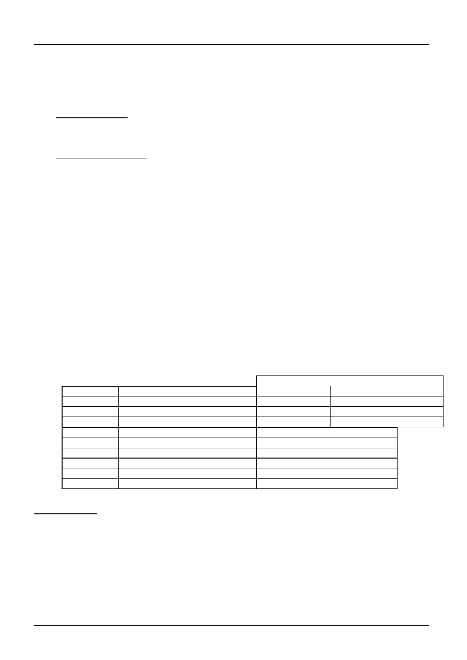
CONNECTION DETAILS
supply type
Supply
Terminal label
Cable colour
Live-Neutral
Reversible or Live-Live
1-phase
L
Brown
To live
to either power conductor
N
Blue
To neutral
to the other power conductor
PE
Green/Yellow
To earth (ground)
to earth (ground)
supply
Terminal label
Cable colour
2- or 3-phase L1
Black
to phase 1
L2
Black
to phase 2
L3
Black
to phase 3 except 2-phase
N
Light Blue
to neutral except delta
PE
Green/Yellow
to earth (ground)
Technical Notes
The furnaces covered by this manual have electronically controlled power limits. Do not attempt to
calculate the Amps from the Wattage. High break capacity fuses should be used. Avoid fast-blow
fuses and magnetic trip circuit breakers - consult Carbolite if in doubt.
Two-phase models use two phases out of a 3-phase+neutral supply. One phase is unused. The
neutral current is equal to the current in one of the used phases.
“Universal” wiring may be applied to certain TZFs – identified by the presence of 6 supply fuses.
This allows customers to convert between certain star and delta supplies – see section 7.9.